HP 9000 rp4410-4 User Service Guide, Fifth Edition - HP 9000 rp4410/4440 - Page 180
Removing and Replacing the I/O Baseboard Locking Lever, System Battery, Battery Notice
 |
View all HP 9000 rp4410-4 manuals
Add to My Manuals
Save this manual to your list of manuals |
Page 180 highlights
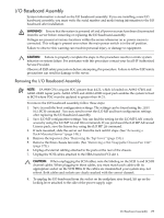
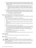
13. If you have installed a new battery on the I/O baseboard assembly or installed a new I/O baseboard assembly, you might need to set the server time and date and restore the iLO MP configuration settings. To set the time and date and restore the iLO MP configuration settings, follow these steps: a. Using the system console, set the system time and date using the BCH DATE command. b. Using the system console, configure the iLO MP. Incorporate settings saved before removing the I/O baseboard assembly or set up the iLO MP as needed. For additional information about using the iLO MP, see the HP Integrity and HP 9000 iLO MP Operations Guide. 14. Verify the system board replacement and operation by using the system utilities. If you have set the time and date and configured the iLO MP, the I/O baseboard assembly is installed and operating correctly. If you have not yet set the time and date or configured the iLO MP: • To verify operation, use the iLO MP commands. • To verify operation, use the BCH commands. Removing and Replacing the I/O Baseboard Locking Lever The I/O baseboard locking lever is comprised of the plastic lever, a label on the lever, and a metal spring inside the lever. To remove the I/O baseboard locking lever, follow these steps: 1. Remove the I/O baseboard assembly. See "Removing the I/O Baseboard Assembly" (page 175). 2. Use a T15 torx screwdriver to remove all three screws from the metal plate on the locking lever. 3. Lift the metal plate off the plastic locking lever (make note of how the plate is positioned on the lever). 4. Keep the metal cover and the screws together. You will use them to install the replacement lever. To replace the I/O baseboard locking lever, follow these steps: 1. Place the metal plate on the locking lever using the position of the screw holes on the locking lever to align with the holes on the metal plate. Make sure to position the metal plate on the lever so the part of the lever with spring fits between the grove on the metal plate. 2. Line the screw hole on the metal plate that is closest to the grove with the mounting hole on the plastic lever. 3. Mount the lever on the standoff making sure to align the holes. 4. Insert and tighten the three screws. 5. Replace the I/O baseboard assembly. See "Replacing the I/O Baseboard Assembly" (page 177). System Battery This section provides information and procedures for replacing the system battery. Battery Notice This product contains a Lithium battery. WARNING! Lithium batteries can explode if mistreated. Do not recharge, disassemble, or dispose of lithium batteries in a fire. Failure to observe this warning can result in personal injury or damage to equipment. Replace the battery with only the identical or equivalent battery. Follow the manufacturer's recommendations. Dispose of used batteries according to the manufacturer's instructions. 180 Removing and Replacing Components
-
 1
1 -
2
-
3
-
4
-
5
-
6
-
7
-
8
-
9
-
10
-
11
-
12
-
13
-
14
-
15
-
16
-
17
-
18
-
19
-
20
-
21
-
22
-
23
-
24
-
25
-
26
-
27
-
28
-
29
-
30
-
31
-
32
-
33
-
34
-
35
-
36
-
37
-
38
-
39
-
40
-
41
-
42
-
43
-
44
-
45
-
46
-
47
-
48
-
49
-
50
-
51
-
52
-
53
-
54
-
55
-
56
-
57
-
58
-
59
-
60
-
61
-
62
-
63
-
64
-
65
-
66
-
67
-
68
-
69
-
70
-
71
-
72
-
73
-
74
-
75
-
76
-
77
-
78
-
79
-
80
-
81
-
82
-
83
-
84
-
85
-
86
-
87
-
88
-
89
-
90
-
91
-
92
-
93
-
94
-
95
-
96
-
97
-
98
-
99
-
100
-
101
-
102
-
103
-
104
-
105
-
106
-
107
-
108
-
109
-
110
-
111
-
112
-
113
-
114
-
115
-
116
-
117
-
118
-
119
-
120
-
121
-
122
-
123
-
124
-
125
-
126
-
127
-
128
-
129
-
130
-
131
-
132
-
133
-
134
-
135
-
136
-
137
-
138
-
139
-
140
-
141
-
142
-
143
-
144
-
145
-
146
-
147
-
148
-
149
-
150
-
151
-
152
-
153
-
154
-
155
-
156
-
157
-
158
-
159
-
160
-
161
-
162
-
163
-
164
-
165
-
166
-
167
-
168
-
169
-
170
-
171
-
172
-
173
-
174
-
 175
175 -
 176
176 -
 177
177 -
 178
178 -
 179
179 -
 180
180 -
 181
181 -
 182
182 -
 183
183 -
 184
184 -
 185
185 -
186
-
187
-
188
-
189
-
190
-
191
-
192
-
193
-
194
-
195
-
196
-
197
-
198
-
199
-
200
-
201
-
202
-
203
-
204
-
205
-
206
-
207
-
208
-
209
-
210
-
211
-
212
-
213
-
214
-
215
-
216
-
217
-
218
-
219
-
220
-
221
-
222
-
223
-
224
-
225
-
226
-
227
-
228
-
229
-
230
-
231
-
232
-
233
-
234
-
235
-
236
-
237
-
238
-
239
-
240
-
241
-
242
-
243
-
244
-
245
-
246
 |
 |