HP 9000 rp4410-4 User Service Guide, Fifth Edition - HP 9000 rp4410/4440 - Page 81
CAUTION, Processor Cable Placed Correctly
 |
View all HP 9000 rp4410-4 manuals
Add to My Manuals
Save this manual to your list of manuals |
Page 81 highlights
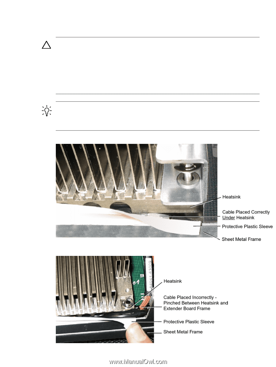
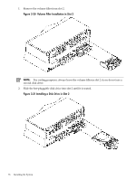
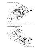
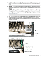
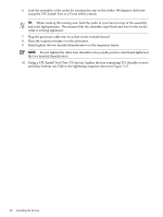
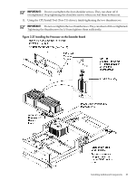
5. Carefully lower the processor, without the sequencer frame, onto the processor socket. Align the pins on the bottom of the heatsink to the slots in the retention frame on the extender board. CAUTION: Do not press the processor modules into the socket. When properly aligned, the processor pins seat into the socket by themselves. You can damage the pins if you apply pressure. CAUTION: Before locking the processor assembly into its socket, ensure that the power cable is not pinched between the heatsink and sheet metal frame of the extender board. Also, ensure that the two power cable ends attached to the dual processor module do not come unplugged from their sockets when you move the cable into place under the heatsink. See Figure 3-25 and Figure 3-26. TIP: Test the alignment of the assembly to the socket by gently moving the assembly back and forth with the palm of your hand-you should feel little or no side play. However, because the assembly is not yet tightened, it can tilt slightly toward the center of the extender board; this is acceptable. Figure 3-25 Processor Cable Placed Correctly Figure 3-26 Processor Cable Placed Incorrectly Installing Additional Components 81
-
 1
1 -
2
-
3
-
4
-
5
-
6
-
7
-
8
-
9
-
10
-
11
-
12
-
13
-
14
-
15
-
16
-
17
-
18
-
19
-
20
-
21
-
22
-
23
-
24
-
25
-
26
-
27
-
28
-
29
-
30
-
31
-
32
-
33
-
34
-
35
-
36
-
37
-
38
-
39
-
40
-
41
-
42
-
43
-
44
-
45
-
46
-
47
-
48
-
49
-
50
-
51
-
52
-
53
-
54
-
55
-
56
-
57
-
58
-
59
-
60
-
61
-
62
-
63
-
64
-
65
-
66
-
67
-
68
-
69
-
70
-
71
-
72
-
73
-
74
-
75
-
 76
76 -
 77
77 -
 78
78 -
 79
79 -
 80
80 -
 81
81 -
 82
82 -
 83
83 -
 84
84 -
 85
85 -
 86
86 -
87
-
88
-
89
-
90
-
91
-
92
-
93
-
94
-
95
-
96
-
97
-
98
-
99
-
100
-
101
-
102
-
103
-
104
-
105
-
106
-
107
-
108
-
109
-
110
-
111
-
112
-
113
-
114
-
115
-
116
-
117
-
118
-
119
-
120
-
121
-
122
-
123
-
124
-
125
-
126
-
127
-
128
-
129
-
130
-
131
-
132
-
133
-
134
-
135
-
136
-
137
-
138
-
139
-
140
-
141
-
142
-
143
-
144
-
145
-
146
-
147
-
148
-
149
-
150
-
151
-
152
-
153
-
154
-
155
-
156
-
157
-
158
-
159
-
160
-
161
-
162
-
163
-
164
-
165
-
166
-
167
-
168
-
169
-
170
-
171
-
172
-
173
-
174
-
175
-
176
-
177
-
178
-
179
-
180
-
181
-
182
-
183
-
184
-
185
-
186
-
187
-
188
-
189
-
190
-
191
-
192
-
193
-
194
-
195
-
196
-
197
-
198
-
199
-
200
-
201
-
202
-
203
-
204
-
205
-
206
-
207
-
208
-
209
-
210
-
211
-
212
-
213
-
214
-
215
-
216
-
217
-
218
-
219
-
220
-
221
-
222
-
223
-
224
-
225
-
226
-
227
-
228
-
229
-
230
-
231
-
232
-
233
-
234
-
235
-
236
-
237
-
238
-
239
-
240
-
241
-
242
-
243
-
244
-
245
-
246
 |
 |