HP 9000 rp4410-4 User Service Guide, Fifth Edition - HP 9000 rp4410/4440 - Page 140
QuickFind Diagnostic Panel LEDs, is wrong with the indicated component.
 |
View all HP 9000 rp4410-4 manuals
Add to My Manuals
Save this manual to your list of manuals |
Page 140 highlights
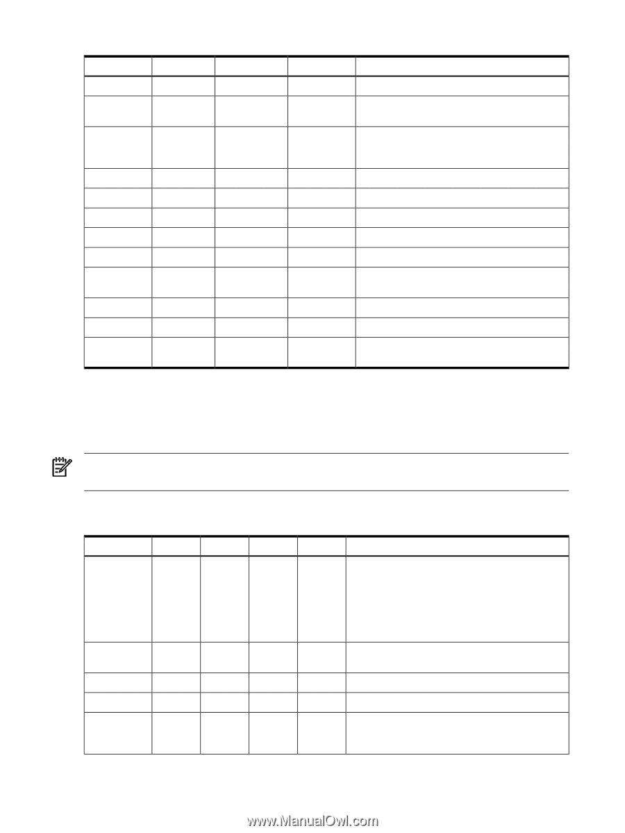
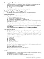
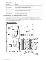
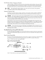
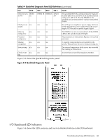
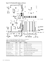
Table 5-3 Front Control Panel LED Definitions LED/Button System LED System LED State Running Booting System LED Attention Flash Rate Color Steady Green Flashing at 0.5 Green Hz Flashing at 1 Hz Yellow System LED System LED Power LED Power LED Power LED Disk LED Fault Off On On Off Active Thermal LED OK Thermal LED Warning Locator Active LED/button Flashing at 2 Hz Red Off N/A Steady Green Flashing at 1 Hz Yellow Off Off Flashing at rate Green of disk activity Steady Green Flashing at 1 Hz Yellow Flashing at 1 Hz Blue Description System normal. OS up and running. OS booting or at BCH. Warning. System needs attention. Redundancy lost, component failure pending. (Additional information can be found in the System Log). Hard fault, system halted. System off. Power normal. Housekeeping voltage present. Power off. Disk activity. Thermal OK. Thermal warning. System locator LED can be remotely or locally activated/deactivated. QuickFind Diagnostic Panel LEDs The QuickFind diagnostic panel is located under the top cover and is attached to the top of the power supply cage. The following definitions describe the status of the various LEDs and what is wrong with the indicated component. NOTE: LED behavior is based on firmware. For changes in LED behavior, see your server firmware release notes. Table 5-4 lists the QuickFind diagnostic panel LED definitions. Table 5-4 QuickFind Diagnostic Panel LED Definitions Item Processor Subsystem I/O VRM CPU VRM Fan module LED 0 Socket 0 CPU board n/a n/a 0 LED 1 LED 2 LED 3 Socket 1 Socket 2 Socket 3 Memory I/O board n/a board n/a n/a n/a n/a n/a n/a 1 2 n/a Details If the System LED (on front panel) is in the attention or fault state and the processor LED is on, then the processor or voltage regulator has failed and the processor module in the specified socket needs to be replaced. If the thermal LED is in the warning or critical state and the processor LED is on, then the processor exceeded the warning or critical level A soldered voltage regulator has failed and the specified board must be replaced n/a n/a One or both fans in a fan module have failed and the module must be replaced. Fan 2 is in front of the power supplies 140 Troubleshooting
-
 1
1 -
2
-
3
-
4
-
5
-
6
-
7
-
8
-
9
-
10
-
11
-
12
-
13
-
14
-
15
-
16
-
17
-
18
-
19
-
20
-
21
-
22
-
23
-
24
-
25
-
26
-
27
-
28
-
29
-
30
-
31
-
32
-
33
-
34
-
35
-
36
-
37
-
38
-
39
-
40
-
41
-
42
-
43
-
44
-
45
-
46
-
47
-
48
-
49
-
50
-
51
-
52
-
53
-
54
-
55
-
56
-
57
-
58
-
59
-
60
-
61
-
62
-
63
-
64
-
65
-
66
-
67
-
68
-
69
-
70
-
71
-
72
-
73
-
74
-
75
-
76
-
77
-
78
-
79
-
80
-
81
-
82
-
83
-
84
-
85
-
86
-
87
-
88
-
89
-
90
-
91
-
92
-
93
-
94
-
95
-
96
-
97
-
98
-
99
-
100
-
101
-
102
-
103
-
104
-
105
-
106
-
107
-
108
-
109
-
110
-
111
-
112
-
113
-
114
-
115
-
116
-
117
-
118
-
119
-
120
-
121
-
122
-
123
-
124
-
125
-
126
-
127
-
128
-
129
-
130
-
131
-
132
-
133
-
134
-
 135
135 -
 136
136 -
 137
137 -
 138
138 -
 139
139 -
 140
140 -
 141
141 -
 142
142 -
 143
143 -
 144
144 -
 145
145 -
146
-
147
-
148
-
149
-
150
-
151
-
152
-
153
-
154
-
155
-
156
-
157
-
158
-
159
-
160
-
161
-
162
-
163
-
164
-
165
-
166
-
167
-
168
-
169
-
170
-
171
-
172
-
173
-
174
-
175
-
176
-
177
-
178
-
179
-
180
-
181
-
182
-
183
-
184
-
185
-
186
-
187
-
188
-
189
-
190
-
191
-
192
-
193
-
194
-
195
-
196
-
197
-
198
-
199
-
200
-
201
-
202
-
203
-
204
-
205
-
206
-
207
-
208
-
209
-
210
-
211
-
212
-
213
-
214
-
215
-
216
-
217
-
218
-
219
-
220
-
221
-
222
-
223
-
224
-
225
-
226
-
227
-
228
-
229
-
230
-
231
-
232
-
233
-
234
-
235
-
236
-
237
-
238
-
239
-
240
-
241
-
242
-
243
-
244
-
245
-
246
 |
 |