HP 9000 rp4410-4 User Service Guide, Fifth Edition - HP 9000 rp4410/4440 - Page 69
Replacing a Hot-Swappable Fan Unit, I/O Baseboard Assembly, Removing the I/O Baseboard Assembly
 |
View all HP 9000 rp4410-4 manuals
Add to My Manuals
Save this manual to your list of manuals |
Page 69 highlights
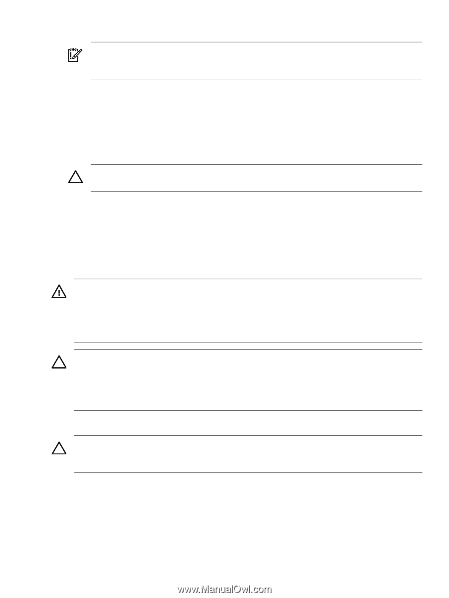
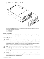
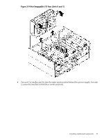
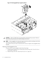
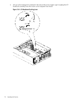
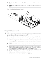
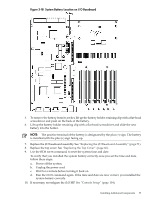
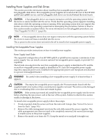
3. Grasp the fan unit locking handle, tilt it up, and pull the fan out from the chassis. (Figure 3-15) IMPORTANT: When one fan unit is removed from the server, the remaining fan units operate at full speed for two minutes. After two minutes a soft-shutdown of the server occurs. Replacing a Hot-Swappable Fan Unit To replace a hot-swappable I/O or power supply fan unit, follow these steps: 1. Orient the fan unit by aligning the appropriate icon on the fan unit handle to the identical icon on the chassis wall. 2. Push the fan unit firmly into the housing and close the handle until flush to the top of the chassis. The fan unit plugs into the power outlet on the system I/O board. CAUTION: If the fan unit handle does not close completely, it is misaligned. Remove the fan unit and check that the alignment icons are oriented correctly. 3. Check the QuickFind diagnostic panel LED indicating the replaced fan unit. See "QuickFind Diagnostic Panel LEDs" (page 123). • When the fan functions normally, the LED is off. • When the fan fails, the LED is lit. 4. Replace the top cover. See "Replacing the Top Cover" (page 66). I/O Baseboard Assembly WARNING! Ensure that the system is powered off and all power sources have been disconnected from the server before removing or replacing the I/O baseboard assembly. Voltages are present at various locations within the server whenever an ac power source is connected. This voltage is present even when the main power switch is in the off position. Failure to observe this warning can result in personal injury or damage to equipment. CAUTION: Failure to properly complete the steps in this procedure results in erratic system behavior or system failure. For assistance with this procedure, contact your local HP Authorized Service Provider. Observe all ESD safety precautions before attempting this procedure. Failure to follow ESD safety precautions can result in damage to the server. Removing the I/O Baseboard Assembly CAUTION: Before removing the I/O baseboard assembly, record all boot configuration settings displayed by the BCH INFO ALL command. You might need to reset the values after replacing the I/O baseboard assembly. To remove the I/O baseboard assembly, follow these steps: 1. If rack-mounted, slide the server out from the rack until it stops. See "Extend the Server from the Rack" (page 58). 2. Remove the top cover. See "Removing the Top Cover" (page 65). 3. Remove the three chassis fan units. See "Removing a Hot-Swappable Fan Unit" (page 68). 4. Unplug all external cabling attached to the ports at the rear of the I/O chassis. 5. Unplug the internal SCSI cables attached to the top of the host bus adapter (HBA) board in PCI slot 1. Installing Additional Components 69
-
 1
1 -
2
-
3
-
4
-
5
-
6
-
7
-
8
-
9
-
10
-
11
-
12
-
13
-
14
-
15
-
16
-
17
-
18
-
19
-
20
-
21
-
22
-
23
-
24
-
25
-
26
-
27
-
28
-
29
-
30
-
31
-
32
-
33
-
34
-
35
-
36
-
37
-
38
-
39
-
40
-
41
-
42
-
43
-
44
-
45
-
46
-
47
-
48
-
49
-
50
-
51
-
52
-
53
-
54
-
55
-
56
-
57
-
58
-
59
-
60
-
61
-
62
-
63
-
 64
64 -
 65
65 -
 66
66 -
 67
67 -
 68
68 -
 69
69 -
 70
70 -
 71
71 -
 72
72 -
 73
73 -
 74
74 -
75
-
76
-
77
-
78
-
79
-
80
-
81
-
82
-
83
-
84
-
85
-
86
-
87
-
88
-
89
-
90
-
91
-
92
-
93
-
94
-
95
-
96
-
97
-
98
-
99
-
100
-
101
-
102
-
103
-
104
-
105
-
106
-
107
-
108
-
109
-
110
-
111
-
112
-
113
-
114
-
115
-
116
-
117
-
118
-
119
-
120
-
121
-
122
-
123
-
124
-
125
-
126
-
127
-
128
-
129
-
130
-
131
-
132
-
133
-
134
-
135
-
136
-
137
-
138
-
139
-
140
-
141
-
142
-
143
-
144
-
145
-
146
-
147
-
148
-
149
-
150
-
151
-
152
-
153
-
154
-
155
-
156
-
157
-
158
-
159
-
160
-
161
-
162
-
163
-
164
-
165
-
166
-
167
-
168
-
169
-
170
-
171
-
172
-
173
-
174
-
175
-
176
-
177
-
178
-
179
-
180
-
181
-
182
-
183
-
184
-
185
-
186
-
187
-
188
-
189
-
190
-
191
-
192
-
193
-
194
-
195
-
196
-
197
-
198
-
199
-
200
-
201
-
202
-
203
-
204
-
205
-
206
-
207
-
208
-
209
-
210
-
211
-
212
-
213
-
214
-
215
-
216
-
217
-
218
-
219
-
220
-
221
-
222
-
223
-
224
-
225
-
226
-
227
-
228
-
229
-
230
-
231
-
232
-
233
-
234
-
235
-
236
-
237
-
238
-
239
-
240
-
241
-
242
-
243
-
244
-
245
-
246
 |
 |