HP 9000 rp4410-4 User Service Guide, Fifth Edition - HP 9000 rp4410/4440 - Page 28
Rear Panel, Table 1-3 Button LED Definitions
 |
View all HP 9000 rp4410-4 manuals
Add to My Manuals
Save this manual to your list of manuals |
Page 28 highlights
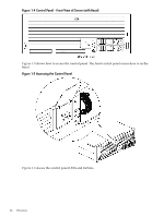
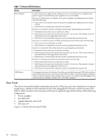
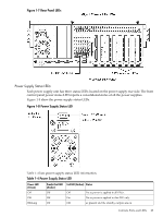
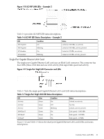
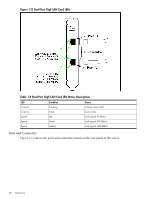
Table 1-3 Button LED Definitions Button Power Button Description Controls the power supply (turns system power on or off) if power is available to the power supply. (Controls both power supplies if two are installed). If power is off but power is available to the power supplies, pressing the power button does the following: • From zero to five seconds, turns on the power supplies and applies power to server circuits. • More than five seconds then released, has no effect. If power is on and the system is at initial system loader, pressing the power button: • Momentarily (less than one second) has no effect. • More than one second, but less than five seconds-do not use. This initiates e-buzzer functions that are not supported in the server. • More than five seconds then released causes an immediate hard power off. If power is on and the system is at BCH, pressing the power button does the following: • From zero to five seconds has no effect. • More than five seconds then released causes an immediate hard power off. If power is on but the OS has been shut down, pressing the power button: • Momentarily (less than one second) has no effect. • More than one second, but less than five seconds-do not use. This initiates e-buzzer functions that are not supported on this server. • More than five seconds then released causes an immediate hard power off. If the OS is running, pressing the power button does the following: • Momentarily (less than one second) has no effect. • More than one second, but less than five seconds-do not use. This initiates e-buzzer functions that are not supported on the server. • More than five seconds then released causes an immediate hard power off. NMI Button Use a paper clip to press this button. Press the non-maskable interrupt (NMI) button before restarting the system after a the system hangs. NMI provides crash dump capture capability. Obtain a system hardware status dump to use in root cause analysis and debugging. The same function is available with the CM>TC iLO MP command. Rear Panel The server rear panel includes communication ports, I/O ports, ac power connectors, two power supply bays, attention LED indicators for the hot-pluggable PCI boards, and the locator LED button. LEDs located on the rear panel of the server signal the operational status of the following components: • Power supplies • iLO MP LAN • Gigabit Ethernet card LAN • PCI slots 3-8 Figure 1-7 shows the rear panel LEDs. 28 Overview
-
 1
1 -
2
-
3
-
4
-
5
-
6
-
7
-
8
-
9
-
10
-
11
-
12
-
13
-
14
-
15
-
16
-
17
-
18
-
19
-
20
-
21
-
22
-
 23
23 -
 24
24 -
 25
25 -
 26
26 -
 27
27 -
 28
28 -
 29
29 -
 30
30 -
 31
31 -
 32
32 -
 33
33 -
34
-
35
-
36
-
37
-
38
-
39
-
40
-
41
-
42
-
43
-
44
-
45
-
46
-
47
-
48
-
49
-
50
-
51
-
52
-
53
-
54
-
55
-
56
-
57
-
58
-
59
-
60
-
61
-
62
-
63
-
64
-
65
-
66
-
67
-
68
-
69
-
70
-
71
-
72
-
73
-
74
-
75
-
76
-
77
-
78
-
79
-
80
-
81
-
82
-
83
-
84
-
85
-
86
-
87
-
88
-
89
-
90
-
91
-
92
-
93
-
94
-
95
-
96
-
97
-
98
-
99
-
100
-
101
-
102
-
103
-
104
-
105
-
106
-
107
-
108
-
109
-
110
-
111
-
112
-
113
-
114
-
115
-
116
-
117
-
118
-
119
-
120
-
121
-
122
-
123
-
124
-
125
-
126
-
127
-
128
-
129
-
130
-
131
-
132
-
133
-
134
-
135
-
136
-
137
-
138
-
139
-
140
-
141
-
142
-
143
-
144
-
145
-
146
-
147
-
148
-
149
-
150
-
151
-
152
-
153
-
154
-
155
-
156
-
157
-
158
-
159
-
160
-
161
-
162
-
163
-
164
-
165
-
166
-
167
-
168
-
169
-
170
-
171
-
172
-
173
-
174
-
175
-
176
-
177
-
178
-
179
-
180
-
181
-
182
-
183
-
184
-
185
-
186
-
187
-
188
-
189
-
190
-
191
-
192
-
193
-
194
-
195
-
196
-
197
-
198
-
199
-
200
-
201
-
202
-
203
-
204
-
205
-
206
-
207
-
208
-
209
-
210
-
211
-
212
-
213
-
214
-
215
-
216
-
217
-
218
-
219
-
220
-
221
-
222
-
223
-
224
-
225
-
226
-
227
-
228
-
229
-
230
-
231
-
232
-
233
-
234
-
235
-
236
-
237
-
238
-
239
-
240
-
241
-
242
-
243
-
244
-
245
-
246
 |
 |