| Section |
Page |
| HP 9000 rp4410 and HP 9000 rp4440 User Service Guide |
1 |
| Table of Contents |
3 |
| About This Document |
17 |
| Intended Audience |
17 |
| New and Changed Information in This Edition |
17 |
| Publishing History |
17 |
| Document Organization |
17 |
| Typographic Conventions |
18 |
| HP-UX Release Name and Release Identifier |
19 |
| Related Documents |
19 |
| HP Encourages Your Comments |
19 |
| 1 Overview |
21 |
| HP 9000 rp4410 and rp4440 Server Views |
21 |
| Detailed Server Description |
23 |
| I/O Subsystem |
23 |
| Internal Core I/O |
23 |
| External Core I/O |
23 |
| Processors |
24 |
| Memory |
24 |
| Cooling |
24 |
| Power Supply Unit |
24 |
| Front Display Panel, DVD, and Diagnostic Panel |
24 |
| Mass Storage |
24 |
| Firmware |
25 |
| Event IDs for Errors and Events |
25 |
| Dimensions and Values |
25 |
| Controls, Ports, and LEDs |
25 |
| Front Panel |
25 |
| Rear Panel |
28 |
| Power Supply Status LEDs |
29 |
| iLO MP LAN LEDs |
30 |
| Single-Port Gigabit Ethernet LAN Card |
31 |
| Ports and Connectors |
32 |
| USB Ports |
33 |
| VGA Port |
33 |
| Serial Ports |
33 |
| iLO MP LAN Port |
34 |
| Gigabit Ethernet LAN Port |
35 |
| SCSI Port, Ultra 3, 68-Pin |
35 |
| Additional Controls and LEDs |
36 |
| Hot-Pluggable Disk Drive LEDs |
36 |
| DVD Drives |
37 |
| QuickFind Diagnostic Panel |
37 |
| Accessing the QuickFind Diagnostic Panel |
37 |
| I/O Baseboard LED Indicators |
38 |
| Powering the Server On and Off |
40 |
| Power States |
40 |
| Powering On the Server |
40 |
| Powering On the Server Using the iLO MP |
40 |
| Powering On the Server Manually |
41 |
| Powering Off the Server |
41 |
| Powering Off the Server Using the iLO MP |
41 |
| Powering Off the Server Manually |
41 |
| 2 System Specifications |
43 |
| System Configuration |
43 |
| Dimensions and Values |
43 |
| Grounding |
44 |
| Electrical Specifications |
44 |
| AC Power Cords |
44 |
| Circuit Breaker |
44 |
| System Power Specifications |
45 |
| Power and Cooling |
46 |
| Environmental Specifications |
46 |
| Operating Environment |
46 |
| Environmental Temperature Sensor |
46 |
| Nonoperating Environment |
47 |
| Cooling |
47 |
| CPU and Memory Cooling |
47 |
| Bulk Power Supply Cooling |
47 |
| PCI and Mass Storage Section Cooling |
47 |
| Acoustic Noise Specification |
48 |
| Physical and Environmental Specifications |
48 |
| 3 Installing the System |
51 |
| Introduction |
51 |
| Server Views |
51 |
| Detailed Server Description |
52 |
| I/O Subsystem |
52 |
| Internal Core I/O |
52 |
| External Core I/O |
53 |
| Processors |
53 |
| Memory |
53 |
| Cooling |
53 |
| Power Supply Unit |
53 |
| Front Display Panel, DVD, and Diagnostic Panel |
54 |
| Mass Storage |
54 |
| Firmware |
54 |
| Event IDs for Errors and Events |
54 |
| Dimensions and Values |
54 |
| Safety Information |
55 |
| Installation Sequence and Checklist |
55 |
| Unpacking and Inspecting the Server |
56 |
| Verifying Site Preparation |
56 |
| Inspecting the Shipping Containers for Damage |
56 |
| Unpacking the Server |
56 |
| Checking the Inventory |
56 |
| Returning Damaged Equipment |
57 |
| Unloading the Server with a Lifter |
57 |
| Installing Additional Components |
57 |
| Service Tools Required |
57 |
| Accessing a Rack-Mounted Server |
58 |
| Extend the Server from the Rack |
58 |
| Inserting the Server Into the Rack |
58 |
| Accessing a Pedestal-Mounted Server |
59 |
| Front Panel Controls and Indicators |
59 |
| Additional Controls and Indicators |
62 |
| Hot-Pluggable Disk Drive Indicators |
62 |
| DVD, DVD-R, and DVD-RW Drives |
63 |
| Front Bezel |
63 |
| Removing the Front Bezel |
63 |
| Replacing the Front Bezel |
64 |
| Front and Top Covers |
64 |
| Removing the Front Cover |
64 |
| Replacing the Front Cover |
65 |
| Removing the Top Cover |
65 |
| Replacing the Top Cover |
66 |
| Hot-Swappable Chassis Fan Units |
66 |
| Removing a Hot-Swappable Fan Unit |
68 |
| Replacing a Hot-Swappable Fan Unit |
69 |
| I/O Baseboard Assembly |
69 |
| Removing the I/O Baseboard Assembly |
69 |
| Replacing the I/O Baseboard Assembly |
71 |
| System Battery |
72 |
| Battery Notice |
72 |
| Replacing the System Battery |
72 |
| Installing Power Supplies and Disk Drives |
74 |
| Installing Hot-Swappable Power Supplies |
74 |
| Power Supply Load Order |
74 |
| Installing Hot-Pluggable Disk Drives |
75 |
| Installing Processors |
77 |
| Required Tools |
77 |
| Dual Processor Modules |
77 |
| Processor Load Order |
78 |
| Removing the Processor Extender Board |
78 |
| Installing a Processor on the Extender Board |
80 |
| Extender Board Switches and Jumpers |
84 |
| Replacing the Processor Extender Board |
84 |
| Installing Memory |
84 |
| Supported DIMM Sizes |
84 |
| DIMM Slot Fillers |
84 |
| Removing a Memory Extender Board |
86 |
| Installing DIMMs |
87 |
| Replacing the Memory Extender Board |
88 |
| Hot-Pluggable PCI/PCI-X |
88 |
| Hot-Pluggable PCI/PCI-X Operations |
89 |
| PCI/PCI-X Hardware and Software Interfaces |
89 |
| PCI/PCI-X Slot Locations and Configurations |
89 |
| Hot-Plug Procedures |
91 |
| OLA |
91 |
| OLR |
95 |
| Understanding LEDs and Hardware Errors |
96 |
| Troubleshooting PCI/PCI-X Hot-Pluggable Operations |
96 |
| Converting SCSI From Simplex to Duplex |
97 |
| Safety Information |
97 |
| Accessing the SCSI Backplane |
97 |
| Converting to Duplex |
97 |
| Replacing the Removed Modules |
101 |
| Installing the Server Into a Rack, Non-HP Rack, or Pedestal |
102 |
| HP Rack |
102 |
| Non-HP Rack |
102 |
| Pedestal Mount |
102 |
| Connecting the Cables |
102 |
| AC Input Power |
102 |
| Core I/O Connections |
103 |
| Applying Standby Power to the Server |
103 |
| Connecting to the LAN |
103 |
| Console Setup |
104 |
| Setting Up the Console |
104 |
| Setup Checklist |
104 |
| Setup Flowchart |
105 |
| Preparation |
106 |
| Determining the Physical iLO MP Access Method |
106 |
| Determining the iLO MP LAN Configuration Method |
107 |
| Configuring the iLO MP LAN Using DHCP and DNS |
107 |
| Configuring the iLO MP LAN Using ARP Ping |
108 |
| Configuring the iLO MP LAN Using the RS-232 Serial Port |
109 |
| Logging In to the iLO MP |
110 |
| Additional Setup |
111 |
| Modifying User Accounts and Default Password |
111 |
| Setting Up Security |
112 |
| Security Access Settings |
112 |
| Accessing the Host Console |
112 |
| Accessing the Host Console With the TUI - CO Command |
112 |
| Interacting with the iLO MP Using the Web GUI |
112 |
| Accessing the Graphic Console Using VGA |
114 |
| Enabling VGA Graphics Capability |
114 |
| Installing Your A6150B Graphics Card |
114 |
| Connecting a Monitor Using the VGA Port |
114 |
| Powering the Server On and Off |
115 |
| Power States |
115 |
| Powering On the Server |
115 |
| Powering On the Server Using the iLO MP PC Command |
115 |
| Powering On the Server Manually |
116 |
| Powering Off the Server |
116 |
| Powering Off the Server Using the iLO MP PC Command |
116 |
| Powering Off the Server Manually |
116 |
| Booting the Operating System |
116 |
| Supported Operating System |
116 |
| Booting and Shutting Down HP-UX |
117 |
| Standard HP-UX Booting Using Boot Console Handler |
117 |
| Booting HP-UX in Single-User Mode |
117 |
| Booting HP-UX in LVM Maintenance Mode |
117 |
| Shutting Down HP-UX |
118 |
| Verifying the Server Configuration Using the Boot Console Handler |
118 |
| Troubleshooting |
118 |
| Troubleshooting Methodology |
118 |
| Troubleshooting Using the Server Power Button |
119 |
| Server Does Not Power On |
119 |
| BCH Menu is Not Available |
120 |
| Operating System Does Not Boot |
120 |
| Operating System Boots with Problems |
120 |
| Intermittent Server Problems |
120 |
| DVD Problems |
121 |
| Hard Drive Problems |
121 |
| Console Problems |
121 |
| Downloading and Installing the Latest Version of the Firmware |
121 |
| Downloading the Latest Version of the Firmware |
121 |
| Installing the Latest Version of the Firmware on the Server |
121 |
| Troubleshooting Using LED Indicators |
122 |
| Front Control Panel LEDs |
122 |
| QuickFind Diagnostic Panel LEDs |
123 |
| Information to Collect Before You Contact Support |
124 |
| 4 Booting the Operating System |
125 |
| Supported Operating System |
125 |
| Booting and Shutting Down HP-UX |
125 |
| Standard HP-UX Booting Using the Boot Console Handler |
125 |
| Booting HP-UX in Single-User Mode |
126 |
| Booting HP-UX in LVM Maintenance Mode |
126 |
| Shutting Down HP-UX |
126 |
| Verifying the Server Configuration Using Boot Console Handler |
127 |
| 5 Troubleshooting |
129 |
| Troubleshooting Methodology |
129 |
| Troubleshooting System Power |
129 |
| Using the Front Panel Power Button |
129 |
| Server Does Not Successfully Power On and Remain Powered On |
130 |
| System Build-Up Troubleshooting |
132 |
| Operating System Boots |
134 |
| Operating System Does Not Boot |
135 |
| Troubleshooting Using Online Support Tools |
135 |
| Support Tools Manager |
135 |
| Event Monitoring Service |
135 |
| iLO MP |
135 |
| Accessing the iLO MP Interface and System Logs |
136 |
| SEL |
136 |
| Troubleshooting Using Offline Support Tools |
137 |
| ODE |
137 |
| Troubleshooting PCI/PCI-X Hot-Pluggable Operations |
138 |
| PCI/PCI-X Bus Mode or Frequency Mismatch |
139 |
| Hardware Operation Fault |
139 |
| Troubleshooting Using LED Indicators |
139 |
| Front Control Panel LEDs |
139 |
| QuickFind Diagnostic Panel LEDs |
140 |
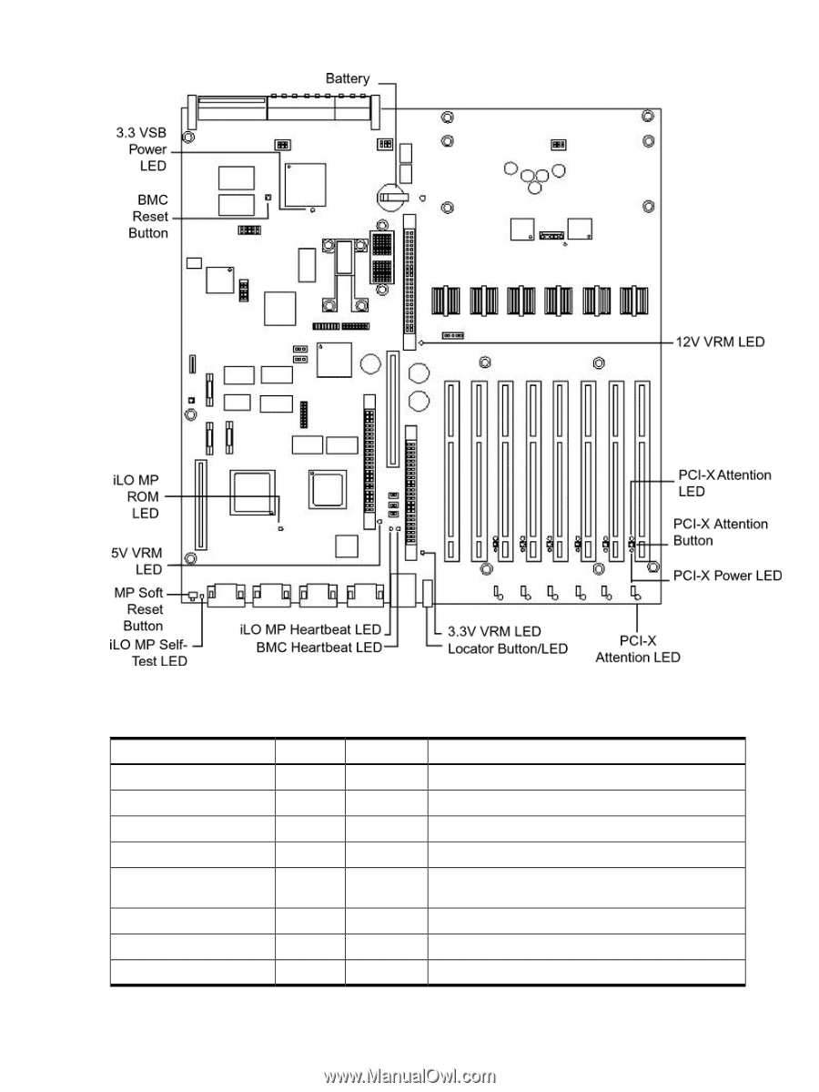
| I/O Baseboard LED Indicators |
141 |
| Memory Extender Boards |
143 |
| Disk and I/O Path Logging |
144 |
| Core I/O Connections |
145 |
| System I/O Board Switches and Jumpers |
146 |
| 6 Removing and Replacing Components |
149 |
| Safety Information |
149 |
| Required Service Tools |
149 |
| Accessing a Rack-Mounted Server |
149 |
| Extend the Server From the Rack |
150 |
| Inserting the Server Into the Rack |
150 |
| Accessing a Pedestal-Mounted Server |
151 |
| Front Bezel |
151 |
| Removing the Front Bezel |
152 |
| Replacing the Front Bezel |
152 |
| Front and Top Covers |
152 |
| Removing the Front Cover |
152 |
| Replacing the Front Cover |
153 |
| Removing the Top Cover |
153 |
| Replacing the Top Cover |
154 |
| Memory Extender Board |
155 |
| Removing the Memory Extender Board |
155 |
| Replacing the Memory Extender Board |
156 |
| System Memory DIMMs |
156 |
| Replacing Deallocated Memory Ranks |
156 |
| Removing Memory DIMMs |
157 |
| Installing Memory DIMMs |
157 |
| Supported DIMM Sizes |
159 |
| DIMM Slot Fillers |
159 |
| Installing DIMMs |
159 |
| Processor Extender Board |
161 |
| Removing the Processor Extender Board |
161 |
| Replacing the Processor Extender Board |
162 |
| Replacing Dual Processor Modules |
165 |
| Dual Processor Modules |
165 |
| Processor Load Order |
165 |
| Removing a Dual Processor Module |
166 |
| Installing a Dual Processor Module |
167 |
| Hot-Swappable Chassis Fan Unit |
172 |
| Removing a Hot-Swappable Chassis Fan Unit |
172 |
| Replacing a Hot-Swappable Chassis Fan Unit |
174 |
| I/O Baseboard Assembly |
175 |
| Removing the I/O Baseboard Assembly |
175 |
| Replacing the I/O Baseboard Assembly |
177 |
| Removing and Replacing the I/O Baseboard Locking Lever |
180 |
| System Battery |
180 |
| Battery Notice |
180 |
| Replacing the System Battery |
181 |
| Removing and Replacing PCI/PCI-X Cards |
182 |
| PCI/PCI-X Configurations |
182 |
| PCI/PCI-X Card Path Logging |
184 |
| OLA |
185 |
| OLR |
189 |
| Removing a PCI/PCI-X Card Offline |
190 |
| Installing a PCI Card Offline |
190 |
| OLX Dividers |
191 |
| Removing an OLX Divider |
191 |
| Replacing an OLX Divider |
194 |
| U320 SCSI Enablement and Conversion Procedures |
194 |
| Time Required |
194 |
| Upgrade Tasks |
194 |
| Simplex Configuration Upgrade |
194 |
| Duplex Configuration Upgrade |
195 |
| Back Up Your Data |
195 |
| Removing Server Components |
195 |
| Removing the SCSI Duplex Board |
195 |
| Removing the SCSI Backplane |
197 |
| Replacing the SCSI Backplane |
199 |
| Installing the SCSI Duplex Board |
199 |
| Installing the Server Components |
201 |
| Verify the Upgrade Installation |
201 |
| Converting SCSI From Duplex to Simplex Operation |
202 |
| Safety Information |
202 |
| Accessing the SCSI Backplane |
202 |
| Converting to Simplex |
202 |
| Installing Server Components |
206 |
| Verifying the Upgrade Installation |
206 |
| Removing and Replacing Core I/O Cards |
207 |
| Safety Information |
207 |
| Required Service Tools |
207 |
| PCI Slot Locations and Configurations |
207 |
| Removing the LAN Core I/O Card |
207 |
| Installing the LAN Core I/O Card |
208 |
| Removing the SCSI Core I/O Card |
209 |
| Installing the SCSI Core I/O Card |
210 |
| Hot-Pluggable Disk Drives |
212 |
| Removing a Hot-Pluggable Disk Drive |
212 |
| Replacing a Hot-Pluggable Disk Drive |
212 |
| SCSI Backplane |
214 |
| Removing the SCSI Backplane |
214 |
| Replacing the SCSI Backplane |
215 |
| Midplane Riser Board |
216 |
| Removing the Midplane Riser Board |
216 |
| Replacing the Midplane Riser Board |
217 |
| Hot-Swappable Power Supplies |
218 |
| Power Supply Load Order |
218 |
| Removing a Hot-Swappable Power Supply |
218 |
| Replacing a Hot-Swappable Power Supply |
219 |
| Power Distribution Board |
220 |
| Removing the Power Distribution Board |
220 |
| Replacing the Power Distribution Board |
221 |
| DVD Drive |
222 |
| Removing a DVD Drive |
222 |
| Replacing a DVD Drive |
223 |
| DVD I/O Board |
224 |
| Removing a DVD I/O Board |
224 |
| Replacing a DVD I/O Board |
225 |
| Display Board |
226 |
| Removing the Display Board |
226 |
| Replacing the Display Board |
227 |
| QuickFind Diagnostic Board |
228 |
| Removing the QuickFind Diagnostic Board |
228 |
| Replacing the QuickFind Diagnostic Board |
229 |
| A Replacement Parts |
231 |
| Customer Self Repair |
231 |
| Replacement Parts List |
232 |
| B Utilities |
235 |
| Boot Console Handler |
235 |
| BCH Commands |
235 |
| BCH Main Menu Commands and Submenus |
236 |
| Boot Command |
236 |
| Path Command |
236 |
| Search Command |
237 |
| Configuration Menu |
237 |
| Information Menu |
238 |
| Service Menu |
238 |
| Display Command |
239 |
| SCSI Command |
239 |
| ProductNum Command |
239 |
| iLO MP |
239 |
| C Physical and Environmental Specifications |
241 |

 1
1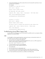 137
137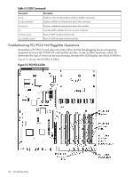 138
138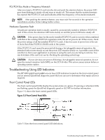 139
139 140
140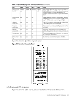 141
141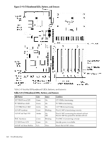 142
142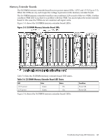 143
143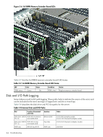 144
144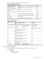 145
145 146
146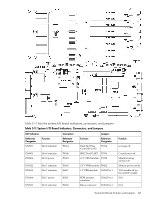 147
147