HP 9000 rp4410-4 User Service Guide, Fifth Edition - HP 9000 rp4410/4440 - Page 195
Duplex Configuration Upgrade, Back Up Your Data, Removing Server Components
 |
View all HP 9000 rp4410-4 manuals
Add to My Manuals
Save this manual to your list of manuals |
Page 195 highlights
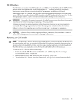
Duplex Configuration Upgrade 1. Back up your data 2. Shutdown the server (disconnect AC power) 3. Remove server components 4. Remove the SCSI duplex board 5. Replace SCSI backplane 6. Install the replacement SCSI duplex board 7. Install server components 8. Verify the upgrade installation Back Up Your Data Before performing the server upgrade, protect yourself by backing up all data and the server OS. In the event of interruptions (for example, power failure or interference), you may need to resume operation in the old configuration before upgrading the server. Back up your data in accordance with local procedures. Always keep a backup copy of the current OS available for emergency use. The OS was provided on CD with the server. You can also obtain a copy from your HP-Information Resource Center (ITRC). Removing Server Components WARNING! Ensure that the system is powered off and all power sources have been disconnected from the server before removing or replacing server components. Voltages are present at various locations within the server whenever an AC power source is connected. This voltage is present even when the main power switch is in the off position. Failure to observe this warning can result in personal injury or damage to equipment. CAUTION: Failure to properly complete the steps in this procedure results in erratic system behavior or system failure. For assistance with this procedure, contact your local HP Authorized Service Provider. Observe all ESD safety precautions before attempting this procedure. Failure to follow ESD safety precautions can result in damage to the server. To remove server components for upgrade, follow these steps: 1. Make sure all users are logged off and that the server is not in use. 2. Perform an orderly shutdown of the server operating system. 3. Press the power button on the server front panel. Verify that the power LED goes off. 4. Disconnect the ac power cords from the server rear panel. 5. Extend the server from the rack. See "Extend the Server From the Rack" (page 150). 6. Remove the front bezel. See "Removing the Front Bezel" (page 152). 7. Remove the front cover. See "Removing the Front Cover" (page 152). 8. Remove the memory extender board. See "Removing the Memory Extender Board" (page 155). 9. Remove the processor extender board. See "Removing the Processor Extender Board" (page 161). Removing the SCSI Duplex Board The SCSI duplex board is only installed if the server is configured for duplex operation. The SCSI duplex board is secured to the disk drive cage by a bracket and connected to the SCSI backplane. U320 SCSI Enablement and Conversion Procedures 195
-
 1
1 -
2
-
3
-
4
-
5
-
6
-
7
-
8
-
9
-
10
-
11
-
12
-
13
-
14
-
15
-
16
-
17
-
18
-
19
-
20
-
21
-
22
-
23
-
24
-
25
-
26
-
27
-
28
-
29
-
30
-
31
-
32
-
33
-
34
-
35
-
36
-
37
-
38
-
39
-
40
-
41
-
42
-
43
-
44
-
45
-
46
-
47
-
48
-
49
-
50
-
51
-
52
-
53
-
54
-
55
-
56
-
57
-
58
-
59
-
60
-
61
-
62
-
63
-
64
-
65
-
66
-
67
-
68
-
69
-
70
-
71
-
72
-
73
-
74
-
75
-
76
-
77
-
78
-
79
-
80
-
81
-
82
-
83
-
84
-
85
-
86
-
87
-
88
-
89
-
90
-
91
-
92
-
93
-
94
-
95
-
96
-
97
-
98
-
99
-
100
-
101
-
102
-
103
-
104
-
105
-
106
-
107
-
108
-
109
-
110
-
111
-
112
-
113
-
114
-
115
-
116
-
117
-
118
-
119
-
120
-
121
-
122
-
123
-
124
-
125
-
126
-
127
-
128
-
129
-
130
-
131
-
132
-
133
-
134
-
135
-
136
-
137
-
138
-
139
-
140
-
141
-
142
-
143
-
144
-
145
-
146
-
147
-
148
-
149
-
150
-
151
-
152
-
153
-
154
-
155
-
156
-
157
-
158
-
159
-
160
-
161
-
162
-
163
-
164
-
165
-
166
-
167
-
168
-
169
-
170
-
171
-
172
-
173
-
174
-
175
-
176
-
177
-
178
-
179
-
180
-
181
-
182
-
183
-
184
-
185
-
186
-
187
-
188
-
189
-
 190
190 -
 191
191 -
 192
192 -
 193
193 -
 194
194 -
 195
195 -
 196
196 -
 197
197 -
 198
198 -
 199
199 -
 200
200 -
201
-
202
-
203
-
204
-
205
-
206
-
207
-
208
-
209
-
210
-
211
-
212
-
213
-
214
-
215
-
216
-
217
-
218
-
219
-
220
-
221
-
222
-
223
-
224
-
225
-
226
-
227
-
228
-
229
-
230
-
231
-
232
-
233
-
234
-
235
-
236
-
237
-
238
-
239
-
240
-
241
-
242
-
243
-
244
-
245
-
246
 |
 |