HP 9000 rp4410-4 User Service Guide, Fifth Edition - HP 9000 rp4410/4440 - Page 95
Olr, Caution, Important
 |
View all HP 9000 rp4410-4 manuals
Add to My Manuals
Save this manual to your list of manuals |
Page 95 highlights
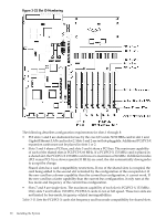
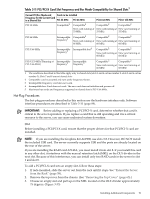
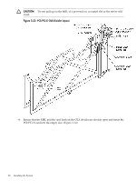
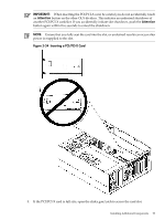
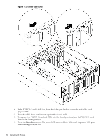
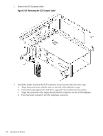
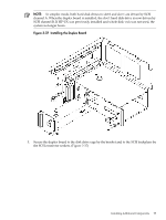
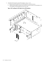
NOTE: After pushing the Attention button, you have five seconds to cancel the operation by pushing the Attention button again. After five seconds, pressing the Attention button initiates slot power off for OLR of the card. 10. Replace the top cover. (See "Replacing the Top Cover" (page 66).) 11. Push the server all the way back into the rack until it stops. OLR CAUTION: For HP-UX 11i v1 (and higher), you must replace an existing card with an identical card. To remove and replace a PCI/PCI-X card into a populated slot, follow these steps: 1. If rack-mounted, slide the server out from the rack until it stops. See "Extend the Server from the Rack" (page 58). 2. Remove the top cover from the chassis. See "Removing the Top Cover" (page 65). 3. Disconnect all external and internal cables attached to the PCI card in the side service bay. 4. Press the Attention button located on the OLX divider that controls the affected slot. The power LED starts to blink. Wait until the power LED goes from blinking to steady off. NOTE: After pushing the Attention button, you have five seconds to cancel the operation by pushing the Attention button again. 5. Turn the PCI/PCI-X card latch approximately 45 degrees on the chassis until the MRL is free to pull up. 6. To turn off power to the slot, pull up on the MRL located on the OLX divider. (Figure 3-33) 7. To completely expose the PCI/PCI-X bulkhead, turn the PCI/PCI-X card latch on the chassis approximately 90 degrees. 8. If the PCI/PCI-X card is full size, open the slider gate latch to release the end of the card. (Figure 3-35) 9. Grasp the top edge of the PCI/PCI-X card and remove it from the slot. NOTE: There is no ejection lever to remove PCI/PCI-X cards as on previous server models. You must remove the PCI/PCI-X card manually. Cutouts in the OLX dividers enable access for grasping PCI/PCI-X cards. 10. Insert the new PCI/PCI-X card into the powered off slot. (Figure 3-34) IMPORTANT: When inserting the PCI/PCI-X card, be careful you do not accidentally touch an Attention button on the other OLX dividers. This initiates an undesired shutdown of another PCI/PCI-X card/slot. If you accidentally initiate slot shutdown, push the Attention button again within five seconds to cancel the shutdown. NOTE: Ensure that you fully seat the card into the slot, or undesired results can occur after power is reapplied to the slot. 11. If the PCI/PCI-X card is full size, close the slider gate latch to secure the end of the card. (Figure 3-33) 12. Push the MRL down until it seats against the chassis wall. 13. Turn the PCI/PCI-X card latch on the chassis to the closed position. This locks the PCI/PCI-X card into its slot and the MRL into the closed position. 14. Press the Attention button. The power LED starts to blink. Installing Additional Components 95
-
 1
1 -
2
-
3
-
4
-
5
-
6
-
7
-
8
-
9
-
10
-
11
-
12
-
13
-
14
-
15
-
16
-
17
-
18
-
19
-
20
-
21
-
22
-
23
-
24
-
25
-
26
-
27
-
28
-
29
-
30
-
31
-
32
-
33
-
34
-
35
-
36
-
37
-
38
-
39
-
40
-
41
-
42
-
43
-
44
-
45
-
46
-
47
-
48
-
49
-
50
-
51
-
52
-
53
-
54
-
55
-
56
-
57
-
58
-
59
-
60
-
61
-
62
-
63
-
64
-
65
-
66
-
67
-
68
-
69
-
70
-
71
-
72
-
73
-
74
-
75
-
76
-
77
-
78
-
79
-
80
-
81
-
82
-
83
-
84
-
85
-
86
-
87
-
88
-
89
-
 90
90 -
 91
91 -
 92
92 -
 93
93 -
 94
94 -
 95
95 -
 96
96 -
 97
97 -
 98
98 -
 99
99 -
 100
100 -
101
-
102
-
103
-
104
-
105
-
106
-
107
-
108
-
109
-
110
-
111
-
112
-
113
-
114
-
115
-
116
-
117
-
118
-
119
-
120
-
121
-
122
-
123
-
124
-
125
-
126
-
127
-
128
-
129
-
130
-
131
-
132
-
133
-
134
-
135
-
136
-
137
-
138
-
139
-
140
-
141
-
142
-
143
-
144
-
145
-
146
-
147
-
148
-
149
-
150
-
151
-
152
-
153
-
154
-
155
-
156
-
157
-
158
-
159
-
160
-
161
-
162
-
163
-
164
-
165
-
166
-
167
-
168
-
169
-
170
-
171
-
172
-
173
-
174
-
175
-
176
-
177
-
178
-
179
-
180
-
181
-
182
-
183
-
184
-
185
-
186
-
187
-
188
-
189
-
190
-
191
-
192
-
193
-
194
-
195
-
196
-
197
-
198
-
199
-
200
-
201
-
202
-
203
-
204
-
205
-
206
-
207
-
208
-
209
-
210
-
211
-
212
-
213
-
214
-
215
-
216
-
217
-
218
-
219
-
220
-
221
-
222
-
223
-
224
-
225
-
226
-
227
-
228
-
229
-
230
-
231
-
232
-
233
-
234
-
235
-
236
-
237
-
238
-
239
-
240
-
241
-
242
-
243
-
244
-
245
-
246
 |
 |
