HP 9000 rp4410-4 User Service Guide, Fifth Edition - HP 9000 rp4410/4440 - Page 25
Firmware, Event IDs for Errors and Events, Dimensions and Values, Controls, Ports, and LEDs
 |
View all HP 9000 rp4410-4 manuals
Add to My Manuals
Save this manual to your list of manuals |
Page 25 highlights
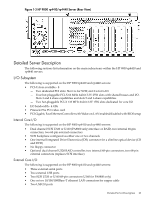
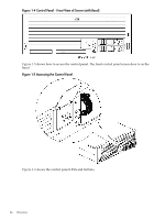
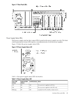
• Maximum internal storage of two 73 MB, 15K drives • Optional integrated HP RAID controller Firmware Firmware consists of many individually linked binary images that are bound together by a single framework at run time. Internally, the firmware employs a software database called a device tree to represent the structure of the hardware platform and to provide a means of associating software elements with hardware functionality. The firmware incorporates the Boot Console Handler (BCH) which provides an interface between the operating system and the platform firmware. BCH uses data tables that contain platform-related information, and boot and run-time service calls available to the operating system and its loader to provide a standard environment for booting. The firmware supports the HP-UX 11i version 1 (or higher) operating system through the HP 9000 processor family standards and extensions, and has no operating system-specific functionality included. The operating system is presented with the same interface to system firmware, and all features are available to the operating system. Event IDs for Errors and Events The server firmware generates event IDs similar to chassis codes for errors, events, and forward progress to the Integrated Light-Out Management Processor (iLO MP) through common shared memory. The iLO MP interprets and stores event IDs. Reviewing these events helps you diagnose and troubleshoot problems with the server. Dimensions and Values Table 1-1 lists the dimensions and their values of the HP 9000 rp4410 and rp4440 servers. Table 1-1 Server Dimensions and Values Dimensions Height Width Depth Weight Value 6.8 in (17.3 cm) 19 in (48.2 cm) 27.2 in (69.0 cm) Unloaded 88 lbs (40 kg) Fully loaded 100 lbs (45.4 kg) Controls, Ports, and LEDs This section describes the controls, ports, and LEDs found on the front panel, rear panel, and internal locations of the HP 9000 rp4410 and rp4440 servers. Front Panel The front panel of the server provides the controls and indicators commonly used for operation. Figure 1-4 shows the control panel on the server front. Dimensions and Values 25
-
 1
1 -
2
-
3
-
4
-
5
-
6
-
7
-
8
-
9
-
10
-
11
-
12
-
13
-
14
-
15
-
16
-
17
-
18
-
19
-
 20
20 -
 21
21 -
 22
22 -
 23
23 -
 24
24 -
 25
25 -
 26
26 -
 27
27 -
 28
28 -
 29
29 -
 30
30 -
31
-
32
-
33
-
34
-
35
-
36
-
37
-
38
-
39
-
40
-
41
-
42
-
43
-
44
-
45
-
46
-
47
-
48
-
49
-
50
-
51
-
52
-
53
-
54
-
55
-
56
-
57
-
58
-
59
-
60
-
61
-
62
-
63
-
64
-
65
-
66
-
67
-
68
-
69
-
70
-
71
-
72
-
73
-
74
-
75
-
76
-
77
-
78
-
79
-
80
-
81
-
82
-
83
-
84
-
85
-
86
-
87
-
88
-
89
-
90
-
91
-
92
-
93
-
94
-
95
-
96
-
97
-
98
-
99
-
100
-
101
-
102
-
103
-
104
-
105
-
106
-
107
-
108
-
109
-
110
-
111
-
112
-
113
-
114
-
115
-
116
-
117
-
118
-
119
-
120
-
121
-
122
-
123
-
124
-
125
-
126
-
127
-
128
-
129
-
130
-
131
-
132
-
133
-
134
-
135
-
136
-
137
-
138
-
139
-
140
-
141
-
142
-
143
-
144
-
145
-
146
-
147
-
148
-
149
-
150
-
151
-
152
-
153
-
154
-
155
-
156
-
157
-
158
-
159
-
160
-
161
-
162
-
163
-
164
-
165
-
166
-
167
-
168
-
169
-
170
-
171
-
172
-
173
-
174
-
175
-
176
-
177
-
178
-
179
-
180
-
181
-
182
-
183
-
184
-
185
-
186
-
187
-
188
-
189
-
190
-
191
-
192
-
193
-
194
-
195
-
196
-
197
-
198
-
199
-
200
-
201
-
202
-
203
-
204
-
205
-
206
-
207
-
208
-
209
-
210
-
211
-
212
-
213
-
214
-
215
-
216
-
217
-
218
-
219
-
220
-
221
-
222
-
223
-
224
-
225
-
226
-
227
-
228
-
229
-
230
-
231
-
232
-
233
-
234
-
235
-
236
-
237
-
238
-
239
-
240
-
241
-
242
-
243
-
244
-
245
-
246
 |
 |