HP 9000 rp4410-4 User Service Guide, Fifth Edition - HP 9000 rp4410/4440 - Page 215
Replacing the SCSI Backplane, SCSI Backplane Removal and Replacement
 |
View all HP 9000 rp4410-4 manuals
Add to My Manuals
Save this manual to your list of manuals |
Page 215 highlights
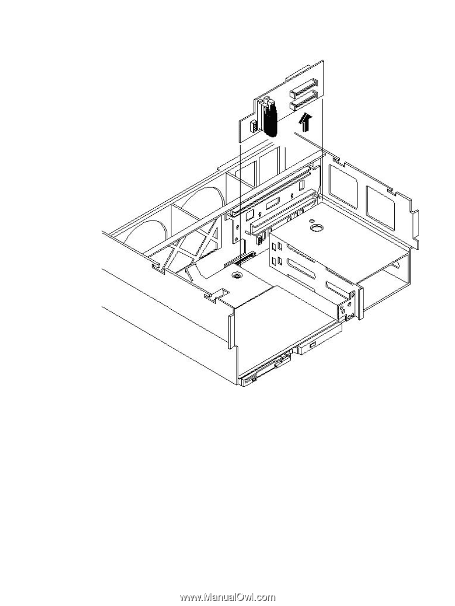
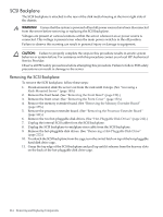
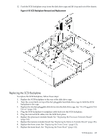
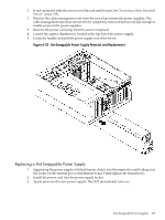
12. Push the SCSI backplane away from the disk drive cage and lift it up and out of the chassis. Figure 6-50 SCSI Backplane Removal and Replacement Replacing the SCSI Backplane To replace the SCSI backplane, follow these steps: 1. Replace the SCSI backplane to the rear of the disk drive cage. 2. Turn the swivel latch on top of the hot-pluggable hard disk drive cage to latch the SCSI backplane to the cage. 3. Replace the two hot-pluggable disk drives into the disk drive cage. See "Hot-Pluggable Disk Drives" (page 212). 4. Plug the SCSI backplane-to-midplane cable back into the SCSI backplane. 5. Plug the internal SCSI cables into the SCSI back plane. 6. Replace the processor extender board. See "Replacing the Processor Extender Board" (page 162). 7. Replace the memory extender board. See "Replacing the Memory Extender Board" (page 156). 8. Replace the front cover. See "Replacing the Front Cover" (page 153). 9. Replace the front bezel. See "Replacing the Front Bezel" (page 152). SCSI Backplane 215
-
 1
1 -
2
-
3
-
4
-
5
-
6
-
7
-
8
-
9
-
10
-
11
-
12
-
13
-
14
-
15
-
16
-
17
-
18
-
19
-
20
-
21
-
22
-
23
-
24
-
25
-
26
-
27
-
28
-
29
-
30
-
31
-
32
-
33
-
34
-
35
-
36
-
37
-
38
-
39
-
40
-
41
-
42
-
43
-
44
-
45
-
46
-
47
-
48
-
49
-
50
-
51
-
52
-
53
-
54
-
55
-
56
-
57
-
58
-
59
-
60
-
61
-
62
-
63
-
64
-
65
-
66
-
67
-
68
-
69
-
70
-
71
-
72
-
73
-
74
-
75
-
76
-
77
-
78
-
79
-
80
-
81
-
82
-
83
-
84
-
85
-
86
-
87
-
88
-
89
-
90
-
91
-
92
-
93
-
94
-
95
-
96
-
97
-
98
-
99
-
100
-
101
-
102
-
103
-
104
-
105
-
106
-
107
-
108
-
109
-
110
-
111
-
112
-
113
-
114
-
115
-
116
-
117
-
118
-
119
-
120
-
121
-
122
-
123
-
124
-
125
-
126
-
127
-
128
-
129
-
130
-
131
-
132
-
133
-
134
-
135
-
136
-
137
-
138
-
139
-
140
-
141
-
142
-
143
-
144
-
145
-
146
-
147
-
148
-
149
-
150
-
151
-
152
-
153
-
154
-
155
-
156
-
157
-
158
-
159
-
160
-
161
-
162
-
163
-
164
-
165
-
166
-
167
-
168
-
169
-
170
-
171
-
172
-
173
-
174
-
175
-
176
-
177
-
178
-
179
-
180
-
181
-
182
-
183
-
184
-
185
-
186
-
187
-
188
-
189
-
190
-
191
-
192
-
193
-
194
-
195
-
196
-
197
-
198
-
199
-
200
-
201
-
202
-
203
-
204
-
205
-
206
-
207
-
208
-
209
-
 210
210 -
 211
211 -
 212
212 -
 213
213 -
 214
214 -
 215
215 -
 216
216 -
 217
217 -
 218
218 -
 219
219 -
 220
220 -
221
-
222
-
223
-
224
-
225
-
226
-
227
-
228
-
229
-
230
-
231
-
232
-
233
-
234
-
235
-
236
-
237
-
238
-
239
-
240
-
241
-
242
-
243
-
244
-
245
-
246
 |
 |