HP 9000 rp4410-4 User Service Guide, Fifth Edition - HP 9000 rp4410/4440 - Page 139
PCI/PCI-X Bus Mode or Frequency Mismatch, Hardware Operation Fault
 |
View all HP 9000 rp4410-4 manuals
Add to My Manuals
Save this manual to your list of manuals |
Page 139 highlights
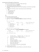
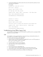
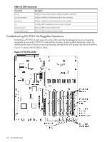
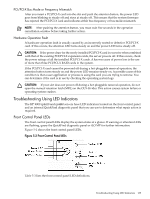
PCI/PCI-X Bus Mode or Frequency Mismatch After you insert a PCI/PCI-X card into the slot and push the attention button, the power LED goes from blinking to steady off and stays at steady off. This means that the system firmware has rejected the PCI/PCI-X card and indicates either bus-frequency or bus-mode mismatch. NOTE: After pushing the attention button, you must wait five seconds in the operation cancellation window before taking further action. Hardware Operation Fault A hardware operation fault is usually caused by an incorrectly seated or defective PCI/PCI-X card. If this occurs, the attention LED turns steady on and the power LED turns steady off. CAUTION: If the power draw for the newly installed PCI/PCI-X card is excessive when combined with that of the existing PCI/PCI-X expansion cards, the server powers off. If this occurs, check the power ratings of all the installed PCI/PCI-X cards. A known cause of power loss is the use of more than three PCI/PCI-X RAID cards in the system. If the PCI/PCI-X card cannot be powered off during a hot-pluggable removal operation, the attention button turns steady on and the power LED remains steady-on. A possible cause of this condition is that a user application or process is using the card you are trying to remove. You can determine if the card is in use by checking the operating system logs. CAUTION: If your slot does not power off during a hot-pluggable removal operation, do not open the manual retention latch (MRL) on the OLX divider. This action causes system failure or operating system crashes. Troubleshooting Using LED Indicators The HP 9000 rp4410 and rp4440 servers have LED indicators located on the front control panel and an internal QuickFind diagnostic panel that you can use to determine what repair action is required. Front Control Panel LEDs The front control panel LEDs display the system status at a glance. If warning or attention LEDs are flashing, query the QuickFind diagnostic panel or iLO MP for further information. Figure 5-2 shows the front control panel LEDs. Figure 5-2 Front Control Panel LEDs Table 5-3 lists the front control panel LED definitions. Troubleshooting Using LED Indicators 139
-
 1
1 -
2
-
3
-
4
-
5
-
6
-
7
-
8
-
9
-
10
-
11
-
12
-
13
-
14
-
15
-
16
-
17
-
18
-
19
-
20
-
21
-
22
-
23
-
24
-
25
-
26
-
27
-
28
-
29
-
30
-
31
-
32
-
33
-
34
-
35
-
36
-
37
-
38
-
39
-
40
-
41
-
42
-
43
-
44
-
45
-
46
-
47
-
48
-
49
-
50
-
51
-
52
-
53
-
54
-
55
-
56
-
57
-
58
-
59
-
60
-
61
-
62
-
63
-
64
-
65
-
66
-
67
-
68
-
69
-
70
-
71
-
72
-
73
-
74
-
75
-
76
-
77
-
78
-
79
-
80
-
81
-
82
-
83
-
84
-
85
-
86
-
87
-
88
-
89
-
90
-
91
-
92
-
93
-
94
-
95
-
96
-
97
-
98
-
99
-
100
-
101
-
102
-
103
-
104
-
105
-
106
-
107
-
108
-
109
-
110
-
111
-
112
-
113
-
114
-
115
-
116
-
117
-
118
-
119
-
120
-
121
-
122
-
123
-
124
-
125
-
126
-
127
-
128
-
129
-
130
-
131
-
132
-
133
-
 134
134 -
 135
135 -
 136
136 -
 137
137 -
 138
138 -
 139
139 -
 140
140 -
 141
141 -
 142
142 -
 143
143 -
 144
144 -
145
-
146
-
147
-
148
-
149
-
150
-
151
-
152
-
153
-
154
-
155
-
156
-
157
-
158
-
159
-
160
-
161
-
162
-
163
-
164
-
165
-
166
-
167
-
168
-
169
-
170
-
171
-
172
-
173
-
174
-
175
-
176
-
177
-
178
-
179
-
180
-
181
-
182
-
183
-
184
-
185
-
186
-
187
-
188
-
189
-
190
-
191
-
192
-
193
-
194
-
195
-
196
-
197
-
198
-
199
-
200
-
201
-
202
-
203
-
204
-
205
-
206
-
207
-
208
-
209
-
210
-
211
-
212
-
213
-
214
-
215
-
216
-
217
-
218
-
219
-
220
-
221
-
222
-
223
-
224
-
225
-
226
-
227
-
228
-
229
-
230
-
231
-
232
-
233
-
234
-
235
-
236
-
237
-
238
-
239
-
240
-
241
-
242
-
243
-
244
-
245
-
246
 |
 |