HP 9000 rp4410-4 User Service Guide, Fifth Edition - HP 9000 rp4410/4440 - Page 156
Replacing the Memory Extender Board, System Memory DIMMs, Replacing Deallocated Memory Ranks
 |
View all HP 9000 rp4410-4 manuals
Add to My Manuals
Save this manual to your list of manuals |
Page 156 highlights
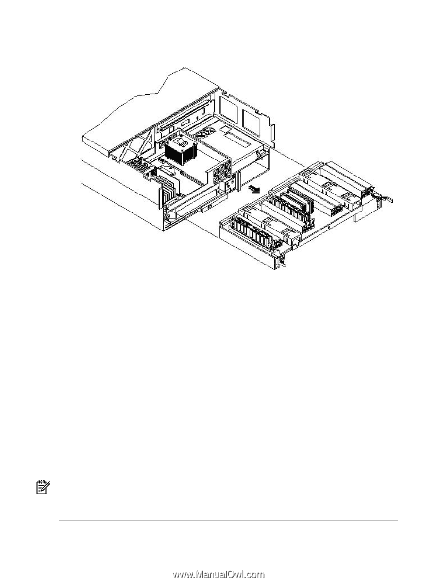
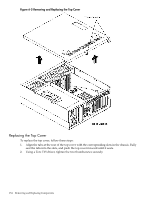
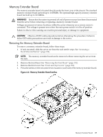
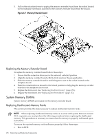
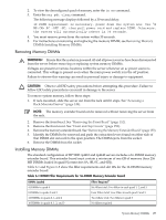
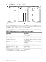
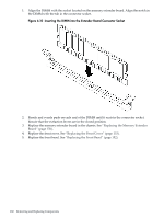
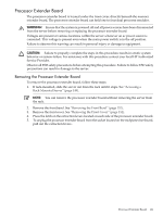
5. Pull on the extraction levers to unplug the memory extender board from the socket located on the midplane riser board and remove the memory extender board from the chassis. Figure 6-7 Memory Extender Board Replacing the Memory Extender Board To replace the memory extender board, follow these steps: 1. Ensure that the extraction levers are in the outward, unlocked position. 2. Align the memory extender board with the front and rear chassis guide slots. 3. Slide the memory extender board in until it begins to seat in the socket located on the midplane board. 4. Push the extraction levers inward to the locked position to fully plug the memory extender board into the midplane riser board. 5. Replace the front cover. See "Replacing the Front Cover" (page 153). 6. Replace the front bezel. See "Replacing the Front Bezel" (page 152). System Memory DIMMs System memory DIMMs are located on the memory extender board. Replacing Deallocated Memory Ranks This section provides the steps necessary to replace deallocated memory ranks. NOTE: When replacing deallocated memory ranks on a server with system firmware version 45.11 or greater, you must perform the following procedure before replacing the deallocated memory. This procedures is necessary to ensure that the memory is properly reallocated upon server boot. To ensure the repaired memory rank reallocates properly, follow these steps: 1. Boot to BCH. 156 Removing and Replacing Components
-
 1
1 -
2
-
3
-
4
-
5
-
6
-
7
-
8
-
9
-
10
-
11
-
12
-
13
-
14
-
15
-
16
-
17
-
18
-
19
-
20
-
21
-
22
-
23
-
24
-
25
-
26
-
27
-
28
-
29
-
30
-
31
-
32
-
33
-
34
-
35
-
36
-
37
-
38
-
39
-
40
-
41
-
42
-
43
-
44
-
45
-
46
-
47
-
48
-
49
-
50
-
51
-
52
-
53
-
54
-
55
-
56
-
57
-
58
-
59
-
60
-
61
-
62
-
63
-
64
-
65
-
66
-
67
-
68
-
69
-
70
-
71
-
72
-
73
-
74
-
75
-
76
-
77
-
78
-
79
-
80
-
81
-
82
-
83
-
84
-
85
-
86
-
87
-
88
-
89
-
90
-
91
-
92
-
93
-
94
-
95
-
96
-
97
-
98
-
99
-
100
-
101
-
102
-
103
-
104
-
105
-
106
-
107
-
108
-
109
-
110
-
111
-
112
-
113
-
114
-
115
-
116
-
117
-
118
-
119
-
120
-
121
-
122
-
123
-
124
-
125
-
126
-
127
-
128
-
129
-
130
-
131
-
132
-
133
-
134
-
135
-
136
-
137
-
138
-
139
-
140
-
141
-
142
-
143
-
144
-
145
-
146
-
147
-
148
-
149
-
150
-
 151
151 -
 152
152 -
 153
153 -
 154
154 -
 155
155 -
 156
156 -
 157
157 -
 158
158 -
 159
159 -
 160
160 -
 161
161 -
162
-
163
-
164
-
165
-
166
-
167
-
168
-
169
-
170
-
171
-
172
-
173
-
174
-
175
-
176
-
177
-
178
-
179
-
180
-
181
-
182
-
183
-
184
-
185
-
186
-
187
-
188
-
189
-
190
-
191
-
192
-
193
-
194
-
195
-
196
-
197
-
198
-
199
-
200
-
201
-
202
-
203
-
204
-
205
-
206
-
207
-
208
-
209
-
210
-
211
-
212
-
213
-
214
-
215
-
216
-
217
-
218
-
219
-
220
-
221
-
222
-
223
-
224
-
225
-
226
-
227
-
228
-
229
-
230
-
231
-
232
-
233
-
234
-
235
-
236
-
237
-
238
-
239
-
240
-
241
-
242
-
243
-
244
-
245
-
246
 |
 |