Insignia NS-FSDVDR User Manual (English) - Page 13
Connecting your TV with an RF modulator, Connecting the basic audio, Connecting to an audio system - manuals
 |
View all Insignia NS-FSDVDR manuals
Add to My Manuals
Save this manual to your list of manuals |
Page 13 highlights
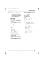
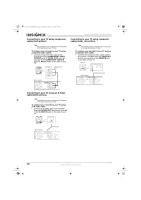
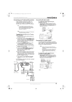
08-1031_NS-FSDVDR.fm Page 11 Wednesday, March 12, 2008 2:53 PM Insignia NS-FSDVDR DVD recorder Connecting your TV with an RF modulator If your TV does not have A/V, S-Video, or component jacks, you can connect your TV using an RF modulator (not supplied). Your recorder does not have a built-in RF modulator. Note This connection provides the poorest picture quality of the connections shown in this guide. If your TV has A/V input jacks, see "Connecting to your TV using composite cables (basic connection)" on page 10. Connecting the basic audio To connect the audio signal from your recorder to your TV: • Connect audio cables (provided) from the AUDIO OUT jacks (left-white and right-red) on your recorder to the AUDIO IN jacks on the back of your TV. R L Note The method you use to connect your TV depends on the type of jacks your TV has. To connect your recorder to your TV using an RF modulator: 1 Disconnect the 75 ohm antenna cable from the back of your TV. 2 Connect the 75 ohm antenna cable from the antenna wall outlet to the ANTENNA IN jack on your recorder. If the antenna input jack of your TV is already being used, disconnect the RF cable from your TV. 3 Connect the ANTENNA OUT jack on your recorder to the RF modulator (usually marked ANT IN) using a 75 ohm RF cable. 4 Connect the RF modulator to your TV using another 75 ohm RF cable. 5 Connect the AUDIO/VIDEO output jacks on your recorder to the AUDIO/VIDEO input jacks of your RF modulator using Audio/Video cables. 6 Set the RF modulator's channel 3/4 switch to either 3 or 4, whichever TV channel is least used in your area. If the RF modulator has a modulator/antenna switch, set it according to the RF modulator's manual. 7 Turn on your TV and switch it to the same channel as you set on the RF modulator (3 or 4). For more details, follow the instructions supplied with the RF modulator. Cable or antenna or Back of recorder IN OUT VIDEO IN IN L R ANTENNA AUDIO IN (L1) COMPONENT VIDEO OUTPUT S-VIDEO Y OUT PB/CB PR/CR VIDEO OUT L R AUDIO OUT Audio/Video cables (provided) RF cable Audio cable Video cable Antenna cable Antenna wall outlet AC 120V ANT IN CHANNEL TO TV 3 4 AUDIO IN VIDEO IN RL RF modulator (not provided) Back of TV Back of recorder Audio cables (L/R) IN OUT VIDEO IN IN L R ANTENNA AUDIO IN (L1) COMPONENT VIDEO OUTPUT S-VIDEO Y OUT PB/CB PR/CR VIDEO OUT DIGITAL AUDIO OUTPUT PCM / BITSTREAM L R AUDIO OUT COAXIAL Connecting to an audio system You can connect your recorder to a standard stereo system or to a Dolby Digital decoder, MD deck, or DAT deck. All devices should be turned off when you change connections. Notes • Playing a DVD using incorrect settings can generate noise distortion and can also damage the speakers. • The audio source on a disc in a Dolby Digital Multi-channel surround format cannot be recorded as digital sound by an MD or DAT deck. To connect the audio signal from your recorder to an audio system: • Connect audio cables (provided) from the AUDIO OUT jacks (left-white and right-red) on your recorder to the AUDIO IN jacks on the back of your stereo system. Stereo system Audio cables (L/R) IN OUT VIDEO IN IN L R ANTENNA AUDIO IN (L1) COMPONENT VIDEO OUTPUT S-VIDEO Y OUT PB/CB PR/CR VIDEO OUT DIGITAL AUDIO OUTPUT PCM / BITSTREAM L R AUDIO OUT COAXIAL Back of recorder - OR - RF cable Back of TV www.insignia-products.com 11
-
 1
1 -
2
-
3
-
4
-
5
-
6
-
7
-
 8
8 -
 9
9 -
 10
10 -
 11
11 -
 12
12 -
 13
13 -
 14
14 -
 15
15 -
 16
16 -
 17
17 -
 18
18 -
19
-
20
-
21
-
22
-
23
-
24
-
25
-
26
-
27
-
28
-
29
-
30
-
31
-
32
-
33
-
34
-
35
-
36
-
37
-
38
-
39
-
40
-
41
-
42
-
43
-
44
-
45
-
46
-
47
-
48
-
49
-
50
-
51
-
52
-
53
-
54
-
55
-
56
-
57
-
58
-
59
-
60
-
61
-
62
-
63
-
64
-
65
-
66
-
67
-
68
-
69
-
70
-
71
-
72
-
73
-
74
-
75
-
76
-
77
-
78
-
79
-
80
-
81
-
82
-
83
-
84
-
85
-
86
-
87
-
88
-
89
-
90
-
91
-
92
-
93
-
94
-
95
-
96
-
97
-
98
-
99
-
100
-
101
-
102
-
103
-
104
-
105
-
106
-
107
-
108
-
109
-
110
-
111
-
112
-
113
-
114
-
115
-
116
 |
 |
