Intel SE7525GP2 Product Specification - Page 125
Platform Management Interconnects
 |
View all Intel SE7525GP2 manuals
Add to My Manuals
Save this manual to your list of manuals |
Page 125 highlights
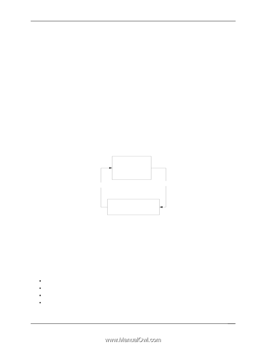
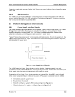
Intel® Server Boards SE7320SP2 and SE7525GP2 Platform Management the system crash state can use the Get NMI Source command to determine and save the cause of the NMI. 5.2.13 SMI Generation The mBMC can generate an SMI due to watchdog timer pre-timeout expiration with SMI pretimeout interrupt specified. The SMI generation is software configurable. The above conditions may or may not be enabled to cause an SMI. 5.3 Platform Management Interconnects 5.3.1 Power Supply Interface Signals The mBMC supports two power supply control signals: Power On and Power Good. The Power On signal connects to the chassis power subsystem and is used to request power state changes (asserted = request Power On). The Power Good signal from the chassis power subsystem indicates current the power state (asserted = power is on). Figure 17 shows the power supply control signals and their sources. To turn the system on, the mBMC asserts the Power On signal and waits for the Power Good signal to assert in response, indicating that DC power is on. mBMC Power Good Power ON Power Sub System Figure 17. Power Supply Control Signals The mBMC uses the Power Good signal to monitor whether the power supply is on and operational, and to confirm whether the actual system power state matches the intended system on/off power state that was commanded with the Power On signal. De-assertion of the Power Good signal generates an interrupt that the mBMC uses to detect either power subsystem failure or loss of AC power. If AC power is suddenly lost, the mBMC: ƒ Immediately asserts system reset ƒ Powers down the system ƒ Waits for configured system off time (depending on configuration) ƒ Attempts to power the system on (depending on configuration) Revision 4.0 113
-
 1
1 -
2
-
3
-
4
-
5
-
6
-
7
-
8
-
9
-
10
-
11
-
12
-
13
-
14
-
15
-
16
-
17
-
18
-
19
-
20
-
21
-
22
-
23
-
24
-
25
-
26
-
27
-
28
-
29
-
30
-
31
-
32
-
33
-
34
-
35
-
36
-
37
-
38
-
39
-
40
-
41
-
42
-
43
-
44
-
45
-
46
-
47
-
48
-
49
-
50
-
51
-
52
-
53
-
54
-
55
-
56
-
57
-
58
-
59
-
60
-
61
-
62
-
63
-
64
-
65
-
66
-
67
-
68
-
69
-
70
-
71
-
72
-
73
-
74
-
75
-
76
-
77
-
78
-
79
-
80
-
81
-
82
-
83
-
84
-
85
-
86
-
87
-
88
-
89
-
90
-
91
-
92
-
93
-
94
-
95
-
96
-
97
-
98
-
99
-
100
-
101
-
102
-
103
-
104
-
105
-
106
-
107
-
108
-
109
-
110
-
111
-
112
-
113
-
114
-
115
-
116
-
117
-
118
-
119
-
 120
120 -
 121
121 -
 122
122 -
 123
123 -
 124
124 -
 125
125 -
 126
126 -
 127
127 -
 128
128 -
 129
129 -
 130
130 -
131
-
132
-
133
-
134
-
135
-
136
-
137
-
138
-
139
-
140
-
141
-
142
-
143
-
144
-
145
-
146
-
147
-
148
-
149
-
150
-
151
-
152
-
153
-
154
-
155
-
156
-
157
-
158
-
159
-
160
-
161
-
162
-
163
-
164
-
165
-
166
-
167
-
168
-
169
-
170
-
171
-
172
-
173
-
174
-
175
-
176
-
177
-
178
-
179
-
180
-
181
-
182
-
183
-
184
 |
 |