Intel SE7525GP2 Product Specification - Page 54
Serial Ports, Serial Port A, Serial Port B, 6.9.3, Floppy Disk Controller, 6.9.4, Keyboard
 |
View all Intel SE7525GP2 manuals
Add to My Manuals
Save this manual to your list of manuals |
Page 54 highlights
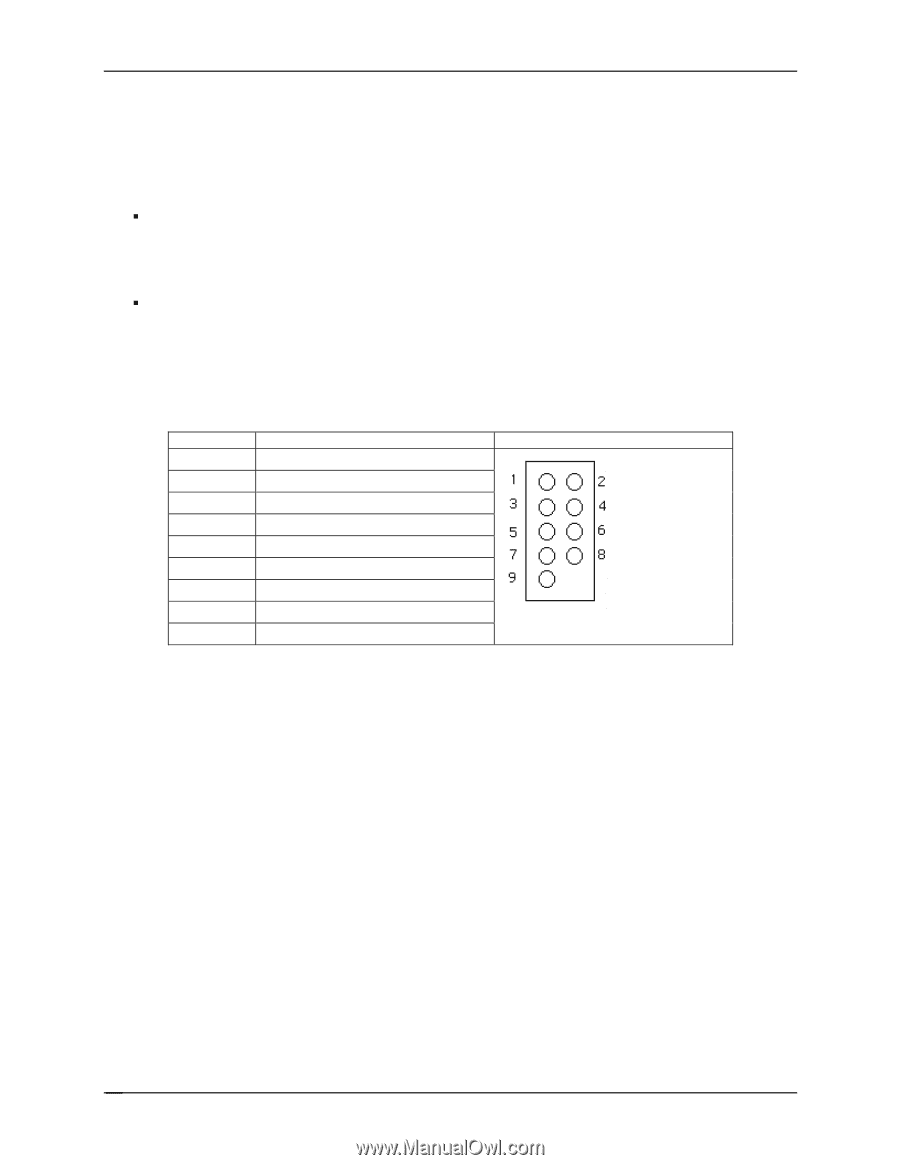
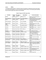
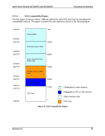
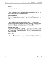
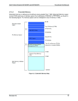
Functional Architecture Intel® Server Boards SE7320SP2 and SE7525GP2 3.6.9.2 Serial Ports Both the SE7320SP2 and Server Board SE7525GP2 provide two serial ports: an external DB9 Serial port, and an internal DH-10 Serial header. The following sub-sections provide details on the use of the serial ports. ƒ Serial Port A Serial A is an external 9-pin DB-9 connector that is located on the back edge of the server board. ƒ Serial Port B Serial B is an optional port, accessed through a 9-pin internal DH-10 header. A standard DH-10 to DB9 cable can be used to direct Serial A out the back of a given chassis. The Serial B interface follows the standard RS232 pin-out as defined in the following table. Pin 1 2 3 4 5 6 7 8 9 DCD DSR RX RTS TX CTS DTR RI GND Table 16. Serial B Header Pin-out Signal Name Serial Port A Header Pin-out 3.6.9.3 Floppy Disk Controller The 34-pin floppy disk controller (FDC) in the SIO is functionally compatible with floppy disk controllers in the DP8473 and N844077. All FDC functions are integrated into the SIO including analog data separator and 16-byte FIFO. 3.6.9.4 Keyboard and Mouse Dual stacked PS/2 ports, located on the back edge of the server board, are provided for keyboard and mouse support. Either port can support a mouse or keyboard. Neither port supports "hot plugging" or connector insertion while the system is turned on. 3.6.9.5 Wake-up Control The Super I/O contains functionality that allows various events to control the power-on and power-off the system. 42 Revision 4.0
-
 1
1 -
2
-
3
-
4
-
5
-
6
-
7
-
8
-
9
-
10
-
11
-
12
-
13
-
14
-
15
-
16
-
17
-
18
-
19
-
20
-
21
-
22
-
23
-
24
-
25
-
26
-
27
-
28
-
29
-
30
-
31
-
32
-
33
-
34
-
35
-
36
-
37
-
38
-
39
-
40
-
41
-
42
-
43
-
44
-
45
-
46
-
47
-
48
-
 49
49 -
 50
50 -
 51
51 -
 52
52 -
 53
53 -
 54
54 -
 55
55 -
 56
56 -
 57
57 -
 58
58 -
 59
59 -
60
-
61
-
62
-
63
-
64
-
65
-
66
-
67
-
68
-
69
-
70
-
71
-
72
-
73
-
74
-
75
-
76
-
77
-
78
-
79
-
80
-
81
-
82
-
83
-
84
-
85
-
86
-
87
-
88
-
89
-
90
-
91
-
92
-
93
-
94
-
95
-
96
-
97
-
98
-
99
-
100
-
101
-
102
-
103
-
104
-
105
-
106
-
107
-
108
-
109
-
110
-
111
-
112
-
113
-
114
-
115
-
116
-
117
-
118
-
119
-
120
-
121
-
122
-
123
-
124
-
125
-
126
-
127
-
128
-
129
-
130
-
131
-
132
-
133
-
134
-
135
-
136
-
137
-
138
-
139
-
140
-
141
-
142
-
143
-
144
-
145
-
146
-
147
-
148
-
149
-
150
-
151
-
152
-
153
-
154
-
155
-
156
-
157
-
158
-
159
-
160
-
161
-
162
-
163
-
164
-
165
-
166
-
167
-
168
-
169
-
170
-
171
-
172
-
173
-
174
-
175
-
176
-
177
-
178
-
179
-
180
-
181
-
182
-
183
-
184
 |
 |