Intel SE7525GP2 Product Specification - Page 126
Power-up Sequence, 3.1.2, Power-down Sequence, 3.1.3, Power Control Sources
 |
View all Intel SE7525GP2 manuals
Add to My Manuals
Save this manual to your list of manuals |
Page 126 highlights
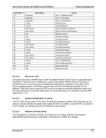
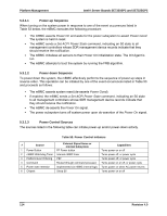
Platform Management Intel® Server Boards SE7320SP2 and SE7525GP2 5.3.1.1 Power-up Sequence When turning on the system power in response to one of the event occurrences listed in Table 53 below, the mBMC executes the following procedure: ƒ The mBMC asserts Power On and waits for the power subsystem to assert Power Good. The system is held in reset. ƒ The mBMC sends a Set ACPI Power State command, indicating an S0 state to all management controllers whose SDR management device records indicate that they should receive the notification. ƒ The mBMC initializes all sensors to their Power On initialization state. The Init Agent is run. ƒ The mBMC attempts to boot the system by running the FRB algorithm. 5.3.1.2 Power-down Sequence To power down the system, the mBMC effectively performs the sequence of power-up steps in reverse order. This operation can be initiated by one of the event occurrences listed in Table 53 and proceeds as follows: ƒ The mBMC asserts system reset (de-asserts Power Good). ƒ If enabled, the mBMC sends a Set ACPI Power State command, indicating an S0 state to all management controllers whose SDR management device records indicate that they should receive the notification. ƒ The mBMC de-asserts the Power On signal. ƒ The power subsystem turns off system power upon de-assertion of the Power On signal. 5.3.1.3 Power Control Sources The sources listed in the following table can initiate power-up and/or power-down activity. Table 53. Power Control Initiators # Source 1 Power Button External Signal Name or Internal Subsystem FP Power button Capabilities Turns power on or off 2 mBMC Watchdog Timer Internal mBMC timer Turns power off, or power cycle 3 Platform Event Filtering PEF Turns power off, or power cycle 4 Command Routed through command processor Turns power on or off, or power cycle 5 Power state retention Implemented via mBMC internal logic Turns power on when AC power returns 6 Chipset Sleep S5 Turns power on or off 114 Revision 4.0
-
 1
1 -
2
-
3
-
4
-
5
-
6
-
7
-
8
-
9
-
10
-
11
-
12
-
13
-
14
-
15
-
16
-
17
-
18
-
19
-
20
-
21
-
22
-
23
-
24
-
25
-
26
-
27
-
28
-
29
-
30
-
31
-
32
-
33
-
34
-
35
-
36
-
37
-
38
-
39
-
40
-
41
-
42
-
43
-
44
-
45
-
46
-
47
-
48
-
49
-
50
-
51
-
52
-
53
-
54
-
55
-
56
-
57
-
58
-
59
-
60
-
61
-
62
-
63
-
64
-
65
-
66
-
67
-
68
-
69
-
70
-
71
-
72
-
73
-
74
-
75
-
76
-
77
-
78
-
79
-
80
-
81
-
82
-
83
-
84
-
85
-
86
-
87
-
88
-
89
-
90
-
91
-
92
-
93
-
94
-
95
-
96
-
97
-
98
-
99
-
100
-
101
-
102
-
103
-
104
-
105
-
106
-
107
-
108
-
109
-
110
-
111
-
112
-
113
-
114
-
115
-
116
-
117
-
118
-
119
-
120
-
 121
121 -
 122
122 -
 123
123 -
 124
124 -
 125
125 -
 126
126 -
 127
127 -
 128
128 -
 129
129 -
 130
130 -
 131
131 -
132
-
133
-
134
-
135
-
136
-
137
-
138
-
139
-
140
-
141
-
142
-
143
-
144
-
145
-
146
-
147
-
148
-
149
-
150
-
151
-
152
-
153
-
154
-
155
-
156
-
157
-
158
-
159
-
160
-
161
-
162
-
163
-
164
-
165
-
166
-
167
-
168
-
169
-
170
-
171
-
172
-
173
-
174
-
175
-
176
-
177
-
178
-
179
-
180
-
181
-
182
-
183
-
184
 |
 |