Intel SE7525GP2 Product Specification - Page 149
Bootblock Initialization Code Checkpoints
 |
View all Intel SE7525GP2 manuals
Add to My Manuals
Save this manual to your list of manuals |
Page 149 highlights
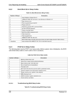
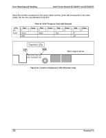
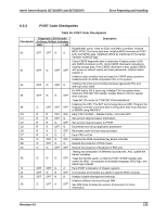
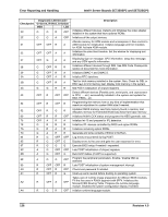
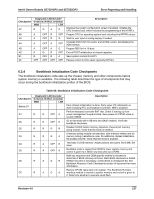
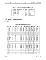
Intel® Server Boards SE7320SP2 and SE7525GP2 Error Reporting and Handling Checkpoint A7 A8 A9 AA AB AC B1 00 Diagnostic LED Decoder G=Green, R=Red, A=Amber MSB LSB R G A G A OFF R OFF A OFF R G A OFF A OFF A A R OFF OFF G OFF OFF A R R OFF G OFF A OFF Description Displays the system configuration screen if enabled. Initialize the CPU's before boot, which includes the programming of the MTRR's. Prepare CPU for operating system boot including final MTRR values. Wait for user input at config display if needed. Uninstall POST INT1Ch vector and INT09h vector. Deinitializes the ADM module. Prepare BBS for Int 19 boot. End of POST initialization of chipset registers. Save system context for ACPI. Passes control to OS Loader (typically INT19h). 6.3.4 Bootblock Initialization Code Checkpoints The bootblock initialization code sets up the chipset, memory and other components before system memory is available. The following table describes the type of checkpoints that may occur during the bootblock initialization portion of the BIOS: Table 66. Bootblock Initialization Code Checkpoints Checkpoint Before D1 D1 D0 D2 D3 D4 D5 D6 D7 Diagnostic LED Decoder G=Green, R=Red, A=Amber MSB LSB R R OFF A R R OFF R R R G R R R G A R A OFF R R A OFF A R A G R R A G A Description Early chipset initialization is done. Early super I/O initialization is done including RTC and keyboard controller. NMI is disabled. Perform keyboard controller BAT test. Check if waking up from power management suspend state. Save power-on CPUID value in scratch CMOS. Go to flat mode with 4 GB limit and GA20 enabled. Verify the bootblock checksum. Disable CACHE before memory detection. Execute full memory sizing module. Verify that flat mode is enabled. If memory sizing module not executed, start memory refresh and do memory sizing in Bootblock code. Do additional chipset initialization. Re-enable CACHE. Verify that flat mode is enabled. Test base 512 KB memory. Adjust policies and cache first 8 MB. Set stack. Bootblock code is copied from ROM to lower system memory and control is given to it. BIOS now executes out of RAM. Both key sequence and OEM specific method is checked to determine if BIOS recovery is forced. Main BIOS checksum is tested. If BIOS recovery is necessary, control flows to checkpoint E0. See Bootblock Recovery Code Checkpoints section of document for more information. Restore CPUID value back into register. The Bootblock-Runtime interface module is moved to system memory and control is given to it. Determine whether to execute serial flash. Revision 4.0 137
-
 1
1 -
2
-
3
-
4
-
5
-
6
-
7
-
8
-
9
-
10
-
11
-
12
-
13
-
14
-
15
-
16
-
17
-
18
-
19
-
20
-
21
-
22
-
23
-
24
-
25
-
26
-
27
-
28
-
29
-
30
-
31
-
32
-
33
-
34
-
35
-
36
-
37
-
38
-
39
-
40
-
41
-
42
-
43
-
44
-
45
-
46
-
47
-
48
-
49
-
50
-
51
-
52
-
53
-
54
-
55
-
56
-
57
-
58
-
59
-
60
-
61
-
62
-
63
-
64
-
65
-
66
-
67
-
68
-
69
-
70
-
71
-
72
-
73
-
74
-
75
-
76
-
77
-
78
-
79
-
80
-
81
-
82
-
83
-
84
-
85
-
86
-
87
-
88
-
89
-
90
-
91
-
92
-
93
-
94
-
95
-
96
-
97
-
98
-
99
-
100
-
101
-
102
-
103
-
104
-
105
-
106
-
107
-
108
-
109
-
110
-
111
-
112
-
113
-
114
-
115
-
116
-
117
-
118
-
119
-
120
-
121
-
122
-
123
-
124
-
125
-
126
-
127
-
128
-
129
-
130
-
131
-
132
-
133
-
134
-
135
-
136
-
137
-
138
-
139
-
140
-
141
-
142
-
143
-
 144
144 -
 145
145 -
 146
146 -
 147
147 -
 148
148 -
 149
149 -
 150
150 -
 151
151 -
 152
152 -
 153
153 -
 154
154 -
155
-
156
-
157
-
158
-
159
-
160
-
161
-
162
-
163
-
164
-
165
-
166
-
167
-
168
-
169
-
170
-
171
-
172
-
173
-
174
-
175
-
176
-
177
-
178
-
179
-
180
-
181
-
182
-
183
-
184
 |
 |