Intel SE7525GP2 Product Specification - Page 145
Checkpoints
 |
View all Intel SE7525GP2 manuals
Add to My Manuals
Save this manual to your list of manuals |
Page 145 highlights
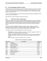
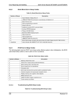
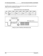
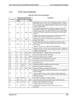
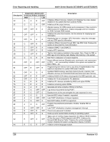
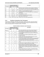
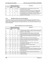
Intel® Server Boards SE7320SP2 and SE7525GP2 Error Reporting and Handling Number of Beeps 1, 2 or 3 4-7, 9-11 8 Troubleshooting Action Reseat the memory, or replace with known good modules. Fatal error indicating a serious problem with the system. Consult your system manufacturer. Before declaring the server board beyond all hope, eliminate the possibility of interference by a malfunctioning add-in card. Remove all expansion cards except the video adapter. - If beep codes are generated even when all other expansion cards are absent, consult your system manufacturer's technical support. - If beep codes are not generated when all other expansion cards are absent, one of the add-in cards is causing the malfunction. Insert the cards back into the system one at a time until the problem happens again. This will reveal the malfunctioning add-in card. If the system video adapter is an add-in card, replace or reseat the video adapter. If the video adapter is an integrated part of the system board, the board may be faulty. 6.2.4 "POST Error Pause" Option In case of POST error(s) that occur during system boot-up, the BIOS will stop and wait for the user to press an appropriate key before booting the operating system or entering BIOS setup. The user can override this option by setting "POST Error Pause" to "disabled" in the BIOS setup Advanced menu page. If the "POST Error Pause" option is set to "disabled", the system will boot the operating system without user intervention. The default value setting for this option is "enabled". 6.3 Checkpoints 6.3.1 System ROM BIOS POST Task Test Point (Port 80h Code) The BIOS sends a 1-byte hex code to port 80 before each task. The port 80 codes provide a troubleshooting method in the event of a system hang during POST. Table 65 provides a list of the Port 80 codes and the corresponding task description. 6.3.2 Diagnostic LEDs All port 80 codes are displayed using the diagnostic LEDs found on the back edge of the server board. The diagnostic LED feature consists of a hardware decoder and four dual color LEDs. During POST, the LEDs will display all normal POST codes representing the progress of the BIOS POST. Each code will be represented by a combination of colors from the four LEDs. The LEDs are capable of displaying three colors: green, red, and amber. The POST codes are divided into two nibbles, an upper nibble and a lower nibble. Each bit in the upper nibble is represented by a red LED and each bit in the lower nibble is represented by a green LED. If both bits are set in the upper and lower nibbles then both red and green LEDs are lit, resulting in an amber color. If both bits are clear, then the LED is off. In the below example, BIOS sends a value of ACh to the diagnostic LED decoder. The LEDs are decoded as follows: ƒ Red bits = 1010b = Ah ƒ Green bits = 1100b = Ch Revision 4.0 133
-
 1
1 -
2
-
3
-
4
-
5
-
6
-
7
-
8
-
9
-
10
-
11
-
12
-
13
-
14
-
15
-
16
-
17
-
18
-
19
-
20
-
21
-
22
-
23
-
24
-
25
-
26
-
27
-
28
-
29
-
30
-
31
-
32
-
33
-
34
-
35
-
36
-
37
-
38
-
39
-
40
-
41
-
42
-
43
-
44
-
45
-
46
-
47
-
48
-
49
-
50
-
51
-
52
-
53
-
54
-
55
-
56
-
57
-
58
-
59
-
60
-
61
-
62
-
63
-
64
-
65
-
66
-
67
-
68
-
69
-
70
-
71
-
72
-
73
-
74
-
75
-
76
-
77
-
78
-
79
-
80
-
81
-
82
-
83
-
84
-
85
-
86
-
87
-
88
-
89
-
90
-
91
-
92
-
93
-
94
-
95
-
96
-
97
-
98
-
99
-
100
-
101
-
102
-
103
-
104
-
105
-
106
-
107
-
108
-
109
-
110
-
111
-
112
-
113
-
114
-
115
-
116
-
117
-
118
-
119
-
120
-
121
-
122
-
123
-
124
-
125
-
126
-
127
-
128
-
129
-
130
-
131
-
132
-
133
-
134
-
135
-
136
-
137
-
138
-
139
-
 140
140 -
 141
141 -
 142
142 -
 143
143 -
 144
144 -
 145
145 -
 146
146 -
 147
147 -
 148
148 -
 149
149 -
 150
150 -
151
-
152
-
153
-
154
-
155
-
156
-
157
-
158
-
159
-
160
-
161
-
162
-
163
-
164
-
165
-
166
-
167
-
168
-
169
-
170
-
171
-
172
-
173
-
174
-
175
-
176
-
177
-
178
-
179
-
180
-
181
-
182
-
183
-
184
 |
 |