Intel SE7525GP2 Product Specification - Page 65
CONFIG_ADDRESS Register
 |
View all Intel SE7525GP2 manuals
Add to My Manuals
Save this manual to your list of manuals |
Page 65 highlights
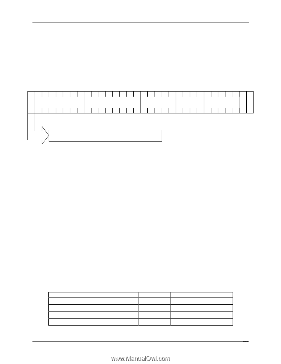
Intel® Server Boards SE7320SP2 and SE7525GP2 Functional Architecture 3.7.3.1 CONFIG_ADDRESS Register CONFIG_ADDRESS is 32 bits wide and contains the field format shown in the following figure. Bits [23::16] choose a specific bus in the system. Bits [15::11] choose a specific device on the selected bus. Bits [10:8] choose a specific function in a multi-function device. Bit [8::2] select a specific register in the configuration space of the selected device or function on the bus. 31 30 24 23 16 15 11 10 8 7 10 Reserved Bus Number Device Function Register 00 Enable bit ('1' = enabled, '0' = disabled) Figure 12. CONFIG_ADDRES Register 3.7.3.1.1 Bus Number PCI configuration space protocol requires that all PCI buses in a system be assigned a Bus Number, Furthermore, bus numbers must be assigned in ascending order within hierarchical buses. Each PCI bridge has registers containing its PCI Bus Number and subordinate PCI Bus Number, which must be loaded by POST code. The Subordinate PCI Bus Number is the bus number of the last hierarchical PCI bus under the current bridge. The PCI Bus Number and the Subordinate PCI Bus Number are the same in the last hierarchical bridge. 3.7.3.1.2 Device Number and IDSEL Mapping Each device under a PCI bridge has its IDSEL input connected to one bit out of the PCI bus address/data signals AD[31::11] for the PCI bus. Each IDSEL-mapped AD bit acts as a chip select for each device on PCI. The host bridge responds to a unique PCI device ID value, that along with the bus number, cause the assertion of IDSEL for a particular device during configuration cycles. The following table shows the correspondence between IDSEL values and PCI device numbers for the PCI bus. The lower 5-bits of the device number are used in CONFIG_ADDRESS bits [15::11]. Table 19. PCI Configuration IDs and Device Numbers PCI Device MCH host-HI bridge/DRAM controller MCH DRAM Controller Error Reporting MCH DMA controller MCH EXP Bridge A0 IDSEL Bus# / Device# / Function# 00 / 00 / 0 00/00/1 00/01/00 00/02/00 Revision 4.0 53
-
 1
1 -
2
-
3
-
4
-
5
-
6
-
7
-
8
-
9
-
10
-
11
-
12
-
13
-
14
-
15
-
16
-
17
-
18
-
19
-
20
-
21
-
22
-
23
-
24
-
25
-
26
-
27
-
28
-
29
-
30
-
31
-
32
-
33
-
34
-
35
-
36
-
37
-
38
-
39
-
40
-
41
-
42
-
43
-
44
-
45
-
46
-
47
-
48
-
49
-
50
-
51
-
52
-
53
-
54
-
55
-
56
-
57
-
58
-
59
-
 60
60 -
 61
61 -
 62
62 -
 63
63 -
 64
64 -
 65
65 -
 66
66 -
 67
67 -
 68
68 -
 69
69 -
 70
70 -
71
-
72
-
73
-
74
-
75
-
76
-
77
-
78
-
79
-
80
-
81
-
82
-
83
-
84
-
85
-
86
-
87
-
88
-
89
-
90
-
91
-
92
-
93
-
94
-
95
-
96
-
97
-
98
-
99
-
100
-
101
-
102
-
103
-
104
-
105
-
106
-
107
-
108
-
109
-
110
-
111
-
112
-
113
-
114
-
115
-
116
-
117
-
118
-
119
-
120
-
121
-
122
-
123
-
124
-
125
-
126
-
127
-
128
-
129
-
130
-
131
-
132
-
133
-
134
-
135
-
136
-
137
-
138
-
139
-
140
-
141
-
142
-
143
-
144
-
145
-
146
-
147
-
148
-
149
-
150
-
151
-
152
-
153
-
154
-
155
-
156
-
157
-
158
-
159
-
160
-
161
-
162
-
163
-
164
-
165
-
166
-
167
-
168
-
169
-
170
-
171
-
172
-
173
-
174
-
175
-
176
-
177
-
178
-
179
-
180
-
181
-
182
-
183
-
184
 |
 |