Intel SE7525GP2 Product Specification - Page 62
I/O Map
 |
View all Intel SE7525GP2 manuals
Add to My Manuals
Save this manual to your list of manuals |
Page 62 highlights
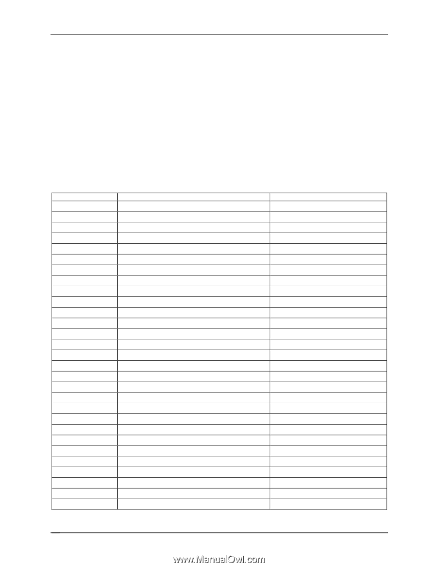
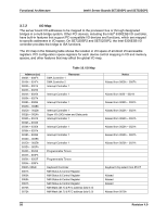
Functional Architecture Intel® Server Boards SE7320SP2 and SE7525GP2 3.7.2 I/O Map The server board I/O addresses to be mapped to the processor bus or through designated bridges in a multi-bridge system. Other PCI devices, including the Intel® 6300ESB I/O controller, have built-in features that support PC-compatible I/O devices and functions, which are mapped to specific addresses in I/O space. On SE7320SP2 and SE7525GP2, the Intel 6300ESB I/O controller provides the bridge to ISA functions. The I/O map in the following table shows the location in I/O space of all direct I/O-accessible registers. PCI configuration space registers for each device control mapping in I/O and memory spaces, and other features that may affect the global I/O map. Address (es) 0000h - 000Fh 0010h - 001Fh 0020h - 0021h 0022h - 0023h 0024h - 0025h 0026h - 0027h 0028h - 0029h 002Ah - 002Bh 002Ch - 002Dh 002Eh - 002Fh 0030h - 0031h 0032h - 0033h 0034h - 0035h 0036h - 0037h 0038h - 0039h 003Ah - 003Bh 003Ch - 003Dh 003Eh - 003Fh 0040h - 0043h 0044h - 004Fh 0050h - 0053F 0054h - 005Fh 0060h, 0064h 0061h 0063h 0065h 0067h 0070h 0072h Table 18. I/O Map Resource DMA Controller 1 DMA Controller 2 Interrupt Controller 1 Interrupt Controller 1 Interrupt Controller 1 Interrupt Controller 1 Super I/O (SIO) index and Data ports Interrupt Controller 1 Interrupt Controller 1 Interrupt Controller 1 Interrupt Controller 1 Programmable Timers Programmable Timers Keyboard Controller NMI Status & Control Register NMI Status & Control Register NMI Status & Control Register NMI Status & Control Register NMI Mask (bit 7) & RTC address (bits 6::0) NMI Mask (bit 7) & RTC address (bits 6::0) Notes Aliased from 0000h - 000Fh Aliased from 0020 - 0021h Aliased from 0020h - 0021h Aliased from 0020h - 0021h Aliased from 0020h - 0021h Aliased from 0020h - 0021h Aliased from 0020h - 0021h Aliased from 0020h - 0021h Keyboard chip select from 87417 Aliased Aliased Aliased Aliased from 0070h 50 Revision 4.0
-
 1
1 -
2
-
3
-
4
-
5
-
6
-
7
-
8
-
9
-
10
-
11
-
12
-
13
-
14
-
15
-
16
-
17
-
18
-
19
-
20
-
21
-
22
-
23
-
24
-
25
-
26
-
27
-
28
-
29
-
30
-
31
-
32
-
33
-
34
-
35
-
36
-
37
-
38
-
39
-
40
-
41
-
42
-
43
-
44
-
45
-
46
-
47
-
48
-
49
-
50
-
51
-
52
-
53
-
54
-
55
-
56
-
 57
57 -
 58
58 -
 59
59 -
 60
60 -
 61
61 -
 62
62 -
 63
63 -
 64
64 -
 65
65 -
 66
66 -
 67
67 -
68
-
69
-
70
-
71
-
72
-
73
-
74
-
75
-
76
-
77
-
78
-
79
-
80
-
81
-
82
-
83
-
84
-
85
-
86
-
87
-
88
-
89
-
90
-
91
-
92
-
93
-
94
-
95
-
96
-
97
-
98
-
99
-
100
-
101
-
102
-
103
-
104
-
105
-
106
-
107
-
108
-
109
-
110
-
111
-
112
-
113
-
114
-
115
-
116
-
117
-
118
-
119
-
120
-
121
-
122
-
123
-
124
-
125
-
126
-
127
-
128
-
129
-
130
-
131
-
132
-
133
-
134
-
135
-
136
-
137
-
138
-
139
-
140
-
141
-
142
-
143
-
144
-
145
-
146
-
147
-
148
-
149
-
150
-
151
-
152
-
153
-
154
-
155
-
156
-
157
-
158
-
159
-
160
-
161
-
162
-
163
-
164
-
165
-
166
-
167
-
168
-
169
-
170
-
171
-
172
-
173
-
174
-
175
-
176
-
177
-
178
-
179
-
180
-
181
-
182
-
183
-
184
 |
 |