Intel SE7525GP2 Product Specification - Page 42
I/O Sub-System
 |
View all Intel SE7525GP2 manuals
Add to My Manuals
Save this manual to your list of manuals |
Page 42 highlights
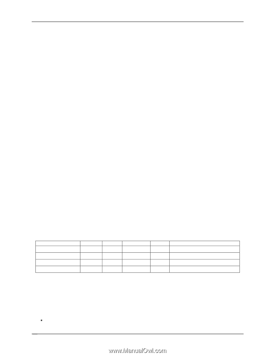
Functional Architecture Intel® Server Boards SE7320SP2 and SE7525GP2 requires that the spare DIMM be at least the size of the largest primary DIMM in use.) The MCH will also begin tracking the progress of its built-in memory scrub engine. Once the scrub engine has covered every location in the primary DIMM, the duplicate write function will have copied every data location to the spare. At that point, the MCH can switch the spare into primary use, and take the failing DIMM off-line. This mechanism requires no software support once it has been programmed and enabled, until the threshold detection has been triggered to request a data copy. Hardware will detect the threshold initiating fail-over, and escalate the occurrence of that event as directed (signal an SMI, generate an interrupt, or wait to be discovered via polling). Whatever software routine responds to the threshold detection must select a victim DIMM (in case multiple DIMMs have crossed the threshold prior to sparing invocation) and initiate the memory copy. Hardware will automatically isolate the "failed" DIMM once the copy has completed. The data copy is accomplished by address aliasing within the DDR control interface, thus it does not require reprogramming of the DRAM row boundary (DRB) registers, nor does it require notification to the operating system that anything has occurred in memory. 3.6 I/O Sub-System The I/O sub-system is made up of several components: the MCH providing the PCI Express* interface and the Intel® 6300ESB I/O controller providing the interface for the onboard video controller, Super I/O chip, and Management Sub-system. This section describes the function of each I/O interface and how they operate on these server boards. 3.6.1 PCI Subsystem The primary I/O interface is PCI, with two independent PCI bus segments. A PCI 33 MHz, 32-bit bus segment (P32-A) with two connectors and a PCI-X 64-bit / 66 MHz segment (P64-A) are controlled through the Intel® 6300ESB I/O controller. Additionally, one x4 PCI Express* (P64Express4) bus segment controlled from the MCH on the Intel Server Board SE7320SP2 is available. Or one x4 PCI Express bus segment and one x16 PCI Express bus segment (P64Express16) are available on the Intel Server Board SE7525GP2. The table below lists the characteristics of the different PCI bus segments. PCI Bus Segment P32-A P64-A P64-Express4 P64-Express16 Table 10. PCI Bus Segment Characteristics Voltage 5 V 3.3 V 1.6 V 1.6 V Width 32-bits 64-bits 64-bits 64-bits Speed 33 MHz 66 MHz x4 x16 Type PCI PCI-X PCI-E PCI-E PCI I/O Card Slots 2 slots 2 slots 1 slot 1 slot (SE7525GP2 only) 3.6.1.1 P32-A: 32-bit, 33-MHz PCI Subsystem All 32-bit, 33-MHz PCI I/O is directed through the Intel® 6300ESB I/O controller. The 32-bit, 33-MHz PCI segment created by the Intel 6300ESB I/O controller is known as the P32-A segment. The P32-A segment supports the following devices: ƒ 2D/3D Graphics Accelerator: ATI* Rage XL video controller 30 Revision 4.0
-
 1
1 -
2
-
3
-
4
-
5
-
6
-
7
-
8
-
9
-
10
-
11
-
12
-
13
-
14
-
15
-
16
-
17
-
18
-
19
-
20
-
21
-
22
-
23
-
24
-
25
-
26
-
27
-
28
-
29
-
30
-
31
-
32
-
33
-
34
-
35
-
36
-
 37
37 -
 38
38 -
 39
39 -
 40
40 -
 41
41 -
 42
42 -
 43
43 -
 44
44 -
 45
45 -
 46
46 -
 47
47 -
48
-
49
-
50
-
51
-
52
-
53
-
54
-
55
-
56
-
57
-
58
-
59
-
60
-
61
-
62
-
63
-
64
-
65
-
66
-
67
-
68
-
69
-
70
-
71
-
72
-
73
-
74
-
75
-
76
-
77
-
78
-
79
-
80
-
81
-
82
-
83
-
84
-
85
-
86
-
87
-
88
-
89
-
90
-
91
-
92
-
93
-
94
-
95
-
96
-
97
-
98
-
99
-
100
-
101
-
102
-
103
-
104
-
105
-
106
-
107
-
108
-
109
-
110
-
111
-
112
-
113
-
114
-
115
-
116
-
117
-
118
-
119
-
120
-
121
-
122
-
123
-
124
-
125
-
126
-
127
-
128
-
129
-
130
-
131
-
132
-
133
-
134
-
135
-
136
-
137
-
138
-
139
-
140
-
141
-
142
-
143
-
144
-
145
-
146
-
147
-
148
-
149
-
150
-
151
-
152
-
153
-
154
-
155
-
156
-
157
-
158
-
159
-
160
-
161
-
162
-
163
-
164
-
165
-
166
-
167
-
168
-
169
-
170
-
171
-
172
-
173
-
174
-
175
-
176
-
177
-
178
-
179
-
180
-
181
-
182
-
183
-
184
 |
 |