Intel SE7525GP2 Product Specification - Page 172
Rolling BIOS Bank Selection Jumper
 |
View all Intel SE7525GP2 manuals
Add to My Manuals
Save this manual to your list of manuals |
Page 172 highlights
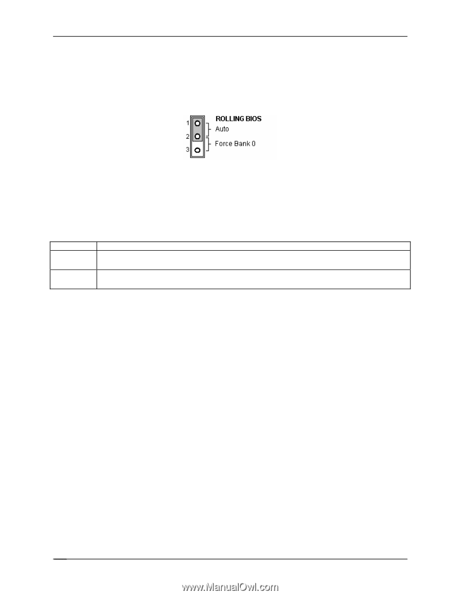
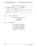
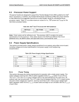
Connector Definitions and Pin-outs Intel® Server Boards SE7320SP2 and SE7525GP2 7.16.2 Rolling BIOS Bank Selection Jumper An additional 3-pin jumper header (J26) is provided to support the Rolling BIOS functionality. This jumper is located near the processor 2 VRD heatsink and the SATA connectors on the board. The jumper provides the option to force the board to boot from Bank 0 as part of the Rolling BIOS feature. The figure below shows the factory default location for the jumper option. Figure 20. BIOS Bank Jumper (J26) The following table describes the jumper option. Option Auto Force Bank0 Table 98. BIOS Bank Jumper Option Description If pins 1 and 2 are jumpered (default), the platform instrumentation on the board controls which BIOS bank has the BIOS the board is intended to boot from. If pins 2 and 3 are jumpered, the server board is forced to boot by using the BIOS code stored in Bank0. 160 Revision 4.0
-
 1
1 -
2
-
3
-
4
-
5
-
6
-
7
-
8
-
9
-
10
-
11
-
12
-
13
-
14
-
15
-
16
-
17
-
18
-
19
-
20
-
21
-
22
-
23
-
24
-
25
-
26
-
27
-
28
-
29
-
30
-
31
-
32
-
33
-
34
-
35
-
36
-
37
-
38
-
39
-
40
-
41
-
42
-
43
-
44
-
45
-
46
-
47
-
48
-
49
-
50
-
51
-
52
-
53
-
54
-
55
-
56
-
57
-
58
-
59
-
60
-
61
-
62
-
63
-
64
-
65
-
66
-
67
-
68
-
69
-
70
-
71
-
72
-
73
-
74
-
75
-
76
-
77
-
78
-
79
-
80
-
81
-
82
-
83
-
84
-
85
-
86
-
87
-
88
-
89
-
90
-
91
-
92
-
93
-
94
-
95
-
96
-
97
-
98
-
99
-
100
-
101
-
102
-
103
-
104
-
105
-
106
-
107
-
108
-
109
-
110
-
111
-
112
-
113
-
114
-
115
-
116
-
117
-
118
-
119
-
120
-
121
-
122
-
123
-
124
-
125
-
126
-
127
-
128
-
129
-
130
-
131
-
132
-
133
-
134
-
135
-
136
-
137
-
138
-
139
-
140
-
141
-
142
-
143
-
144
-
145
-
146
-
147
-
148
-
149
-
150
-
151
-
152
-
153
-
154
-
155
-
156
-
157
-
158
-
159
-
160
-
161
-
162
-
163
-
164
-
165
-
166
-
 167
167 -
 168
168 -
 169
169 -
 170
170 -
 171
171 -
 172
172 -
 173
173 -
 174
174 -
 175
175 -
 176
176 -
 177
177 -
178
-
179
-
180
-
181
-
182
-
183
-
184
 |
 |