Intel SE7525GP2 Product Specification - Page 17
Port-80 diagnostic LEDs displaying POST Codes - supported processors
 |
View all Intel SE7525GP2 manuals
Add to My Manuals
Save this manual to your list of manuals |
Page 17 highlights
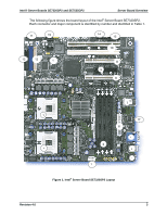
Intel® Server Boards SE7320SP2 and SE7525GP2 Server Board Overview ƒ SSI-compliant front panel headers ƒ SSI-compliant 24-pin main power connector (will support ATX-12V standard in first 20 pins) ƒ Internal expansion connectors ƒ One x16 PCI Express* graphics connector ƒ One x 8 PCI Express connector (on x4 PCI Express bus) ƒ Two 32-bit / 33-MHz PCI connectors ƒ Two 64-bit / 66-MHz PCI-X* connectors ƒ Intel® Light-Guided Diagnostics on most FRU devices (processors, memory) ƒ Port-80 diagnostic LEDs displaying POST Codes The following figure shows the board layout of the Intel® Server Board SE7525GP2. Each connector and major component is identified by number and identified in Table 2. Revision 4.0 5
-
 1
1 -
2
-
3
-
4
-
5
-
6
-
7
-
8
-
9
-
10
-
11
-
 12
12 -
 13
13 -
 14
14 -
 15
15 -
 16
16 -
 17
17 -
 18
18 -
 19
19 -
 20
20 -
 21
21 -
 22
22 -
23
-
24
-
25
-
26
-
27
-
28
-
29
-
30
-
31
-
32
-
33
-
34
-
35
-
36
-
37
-
38
-
39
-
40
-
41
-
42
-
43
-
44
-
45
-
46
-
47
-
48
-
49
-
50
-
51
-
52
-
53
-
54
-
55
-
56
-
57
-
58
-
59
-
60
-
61
-
62
-
63
-
64
-
65
-
66
-
67
-
68
-
69
-
70
-
71
-
72
-
73
-
74
-
75
-
76
-
77
-
78
-
79
-
80
-
81
-
82
-
83
-
84
-
85
-
86
-
87
-
88
-
89
-
90
-
91
-
92
-
93
-
94
-
95
-
96
-
97
-
98
-
99
-
100
-
101
-
102
-
103
-
104
-
105
-
106
-
107
-
108
-
109
-
110
-
111
-
112
-
113
-
114
-
115
-
116
-
117
-
118
-
119
-
120
-
121
-
122
-
123
-
124
-
125
-
126
-
127
-
128
-
129
-
130
-
131
-
132
-
133
-
134
-
135
-
136
-
137
-
138
-
139
-
140
-
141
-
142
-
143
-
144
-
145
-
146
-
147
-
148
-
149
-
150
-
151
-
152
-
153
-
154
-
155
-
156
-
157
-
158
-
159
-
160
-
161
-
162
-
163
-
164
-
165
-
166
-
167
-
168
-
169
-
170
-
171
-
172
-
173
-
174
-
175
-
176
-
177
-
178
-
179
-
180
-
181
-
182
-
183
-
184
 |
 |
Intel® Server Boards SE7320SP2 and SE7525GP2
Server Board Overview
Revision 4.0
5
SSI-compliant front panel headers
SSI-compliant 24-pin main power connector (will support ATX-12V standard in first 20
pins)
Internal expansion connectors
One x16 PCI Express* graphics connector
One x 8 PCI Express connector (on x4 PCI Express bus)
Two 32-bit / 33-MHz PCI connectors
Two 64-bit / 66-MHz PCI-X* connectors
Intel
®
Light-Guided Diagnostics on most FRU devices (processors, memory)
Port-80 diagnostic LEDs displaying POST Codes
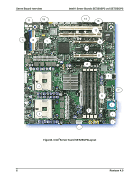
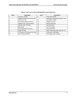
The following figure shows the board layout of the Intel
®
Server Board SE7525GP2. Each
connector and major component is identified by number and identified in Table 2.