Intel SE7525GP2 Product Specification - Page 132
FRU Information
 |
View all Intel SE7525GP2 manuals
Add to My Manuals
Save this manual to your list of manuals |
Page 132 highlights
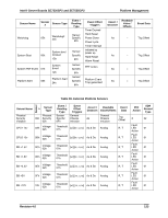
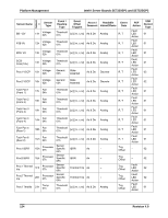
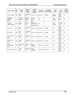
Platform Management Intel® Server Boards SE7320SP2 and SE7525GP2 If it is enabled, Secure Mode can be controlled via the Secure Mode KB signal from the keyboard controller. When Secure Mode is active, pressing a protected front panel switch generates a Secure Mode Violation event. Specifically, this generates an assertion of the Secure Mode Violation Attempt offset of the mBMC's Platform Security Violation Attempt sensor. The Secure Mode state is cleared whenever AC power or system power is applied, when a system reset occurs, or when a mBMC reset occurs. The Secure Mode state includes the bits that specify the actions that are to be taken when Secure Mode is active, as well as the Force Secure Mode On bit. The Set Secure Mode Options command allows specific front panel switches to be protected irrespective of Secure Mode state. See the command definition in the IPMI v1.5 specification for details. The NMI switch can be locked using the Set Secure Mode Options command but is never protected by Secure Mode. This allows a system to be recovered from a hung state when Secure Mode is active 5.3.6 FRU Information The platform management architecture supports providing FRU (field replaceable unit) information for the server board and major replaceable modules in the chassis. 'Major Module' is defined as any circuit board in the system containing active electronic circuitry. FRU information includes board serial number, part number, name, asset tag, and other information. FRUs that contain a management controller use the controller to provide access to the FRU information. FRUs that lack a management controller can make their FRU information available via a SEEPROM directly connected to the IPMB or a private I2C bus. This allows the system integrator to provide a chassis FRU device without having to implement a management controller. This information can be accessed via IPMI FRU commands or using Master WriteRead commands. The mBMC implements the interface for logical FRU inventory devices as specified in the Intelligent Platform Management Interface Specification, Version 1.5. This functionality provides commands used for accessing and managing the FRU inventory information associated with the mBMC (FRU ID 0). These commands can be delivered via all interfaces. 5.3.6.1 mBMC FRU Inventory Area Format The mBMC FRU inventory area format follows the Platform Management FRU Information Storage Definition. Refer to Platform Management FRU Information Storage Definition, Version 1.0 for details. The mBMC provides only low-level access to the FRU inventory area storage. It does not validate or interpret the data that are written. This includes the common header area. Applications cannot relocate or resize any FRU inventory areas. The server board's FRU information is kept in the mBMC internal flash memory. 120 Revision 4.0
-
 1
1 -
2
-
3
-
4
-
5
-
6
-
7
-
8
-
9
-
10
-
11
-
12
-
13
-
14
-
15
-
16
-
17
-
18
-
19
-
20
-
21
-
22
-
23
-
24
-
25
-
26
-
27
-
28
-
29
-
30
-
31
-
32
-
33
-
34
-
35
-
36
-
37
-
38
-
39
-
40
-
41
-
42
-
43
-
44
-
45
-
46
-
47
-
48
-
49
-
50
-
51
-
52
-
53
-
54
-
55
-
56
-
57
-
58
-
59
-
60
-
61
-
62
-
63
-
64
-
65
-
66
-
67
-
68
-
69
-
70
-
71
-
72
-
73
-
74
-
75
-
76
-
77
-
78
-
79
-
80
-
81
-
82
-
83
-
84
-
85
-
86
-
87
-
88
-
89
-
90
-
91
-
92
-
93
-
94
-
95
-
96
-
97
-
98
-
99
-
100
-
101
-
102
-
103
-
104
-
105
-
106
-
107
-
108
-
109
-
110
-
111
-
112
-
113
-
114
-
115
-
116
-
117
-
118
-
119
-
120
-
121
-
122
-
123
-
124
-
125
-
126
-
 127
127 -
 128
128 -
 129
129 -
 130
130 -
 131
131 -
 132
132 -
 133
133 -
 134
134 -
 135
135 -
 136
136 -
 137
137 -
138
-
139
-
140
-
141
-
142
-
143
-
144
-
145
-
146
-
147
-
148
-
149
-
150
-
151
-
152
-
153
-
154
-
155
-
156
-
157
-
158
-
159
-
160
-
161
-
162
-
163
-
164
-
165
-
166
-
167
-
168
-
169
-
170
-
171
-
172
-
173
-
174
-
175
-
176
-
177
-
178
-
179
-
180
-
181
-
182
-
183
-
184
 |
 |