| Section |
Page |
| 1. Introduction |
13 |
| 1.1 Chapter Outline |
13 |
| 1.2 Server Board Use Disclaimer |
13 |
| 2. Server Board Overview |
14 |
| 2.1 Intel® Server Board SE7320SP2 |
14 |
| 2.1.1 Intel® Server Board SE7320SP2 Feature Set |
14 |
| 2.2 Intel® Server Board SE7525GP2 |
16 |
| 2.2.1 Intel® Server Board SE7525GP2 Feature Set |
16 |
| 3. Functional Architecture |
20 |
| 3.1 Processor Sub-system |
21 |
| 3.1.1 Processor Voltage Regulator Devices (VRDs) |
22 |
| 3.1.2 Reset Configuration Logic |
22 |
| 3.1.3 Processor Module Presence Detection |
22 |
| 3.1.4 GTL2006 |
22 |
| 3.1.5 Common Enabling Kit (CEK) Design Support |
23 |
| 3.1.6 Processor Support |
24 |
| 3.1.6.1 Processor Mis-population Detection |
24 |
| 3.1.6.2 Mixed Processor Steppings |
25 |
| 3.1.6.3 Mixed Processor Models |
25 |
| 3.1.6.4 Mixed Processor Families |
25 |
| 3.1.6.5 Mixed Processor Cache Sizes |
25 |
| 3.1.6.6 Jumperless Processor Speed Settings |
25 |
| 3.1.6.7 Microcode |
25 |
| 3.1.6.8 Processor Cache |
25 |
| 3.1.6.9 Hyper-Threading Technology |
26 |
| 3.1.6.10 Intel SpeedStep® Technology |
26 |
| 3.1.6.11 Intel® Extended Memory 64 Technology (Intel® EM64T) Support |
26 |
| 3.1.6.12 Execute Disable Bit support |
26 |
| 3.1.7 Multiple Processor Initialization |
26 |
| 3.1.8 CPU Thermal Sensors |
27 |
| 3.1.9 Processor Thermal Control Sensor |
27 |
| 3.1.10 Processor Thermal Trip Shutdown |
27 |
| 3.1.11 Processor IERR |
27 |
| 3.2 Intel® E7320 Chipset (Intel® Server Board SE7320SP2) |
27 |
| 3.2.1 Memory Controller Hub (MCH) |
28 |
| 3.2.1.1 Front Side Bus (FSB) |
28 |
| 3.2.1.2 MCH Memory Sub-System Overview |
28 |
| 3.2.1.3 PCI Express* |
29 |
| 3.2.1.4 Hub Interface |
29 |
| 3.3 Intel® E7525 Chipset (Intel® Server Board SE7525GP2) |
29 |
| 3.3.1 Memory Controller Hub (MCH) |
30 |
| 3.3.1.1 Front Side Bus (FSB) |
30 |
| 3.3.1.2 MCH Memory Sub-System Overview |
30 |
| 3.3.1.3 PCI Express* |
31 |
| 3.3.1.4 Hub Interface |
31 |
| 3.4 Intel® 6300ESB ICH |
31 |
| 3.4.1 PCI Interface |
32 |
| 3.4.2 IDE Interface (Bus Master Capability and Synchronous DMA Mode) |
32 |
| 3.4.3 SATA Controller |
32 |
| 3.4.4 Low Pin Count (LPC) Interface |
32 |
| 3.4.5 Compatibility Modules (DMA Controller, Timer/Counters, Interrupt Controller) |
32 |
| 3.4.6 Advanced Programmable Interrupt Controller (APIC) |
33 |
| 3.4.7 Universal Serial Bus (USB) Controller |
33 |
| 3.4.8 RTC |
33 |
| 3.4.9 GPIO |
33 |
| 3.4.10 Enhanced Power Management |
34 |
| 3.4.11 System Management Bus (SMBus 2.0) |
34 |
| 3.5 Memory Sub-System |
34 |
| 3.5.1 Memory Sizing |
34 |
| 3.5.2 Memory Population |
35 |
| 3.5.3 I2C Bus |
37 |
| 3.5.4 Disabling DIMMs |
38 |
| 3.5.4.1 Mechanism for CME/SEC Counter |
38 |
| 3.5.5 Memory RASUM Features |
39 |
| 3.5.5.1 DRAM ECC – Intel® x4 Single Device Data Correction (x4 SDDC) |
40 |
| 3.5.5.2 Integrated Memory Scrub Engine |
40 |
| 3.5.5.3 Retry on Uncorrectable Error |
40 |
| 3.5.5.4 Integrated Memory Initialization Engine |
41 |
| 3.5.5.5 DIMM Sparing Function |
41 |
| 3.6 I/O Sub-System |
42 |
| 3.6.1 PCI Subsystem |
42 |
| 3.6.1.1 P32-A: 32-bit, 33-MHz PCI Subsystem |
42 |
| 3.6.1.2 P64-A: 64-bit, 66 MHz PCI Subsystem |
43 |
| 3.6.1.3 P64-Express4: x4 PCI Express* Bus Segment |
43 |
| 3.6.1.4 P64-Express16: x16 PCI Express bus segment |
43 |
| 3.6.1.5 Scan Order |
43 |
| 3.6.1.6 Resource Assignment |
43 |
| 3.6.1.7 Automatic IRQ Assignment |
43 |
| 3.6.1.8 Option ROM Support |
43 |
| 3.6.1.9 PCI APIs |
44 |
| 3.6.2 Split Option ROM |
44 |
| 3.6.3 Interrupt Routing |
44 |
| 3.6.3.1 Legacy Interrupt Routing |
44 |
| 3.6.3.2 APIC Interrupt Routing |
44 |
| 3.6.3.3 Legacy Interrupt Sources |
45 |
| 3.6.3.4 Serialized IRQ Support |
45 |
| 3.6.3.5 IRQ Scan for PCI IRQ |
45 |
| 3.6.4 IDE Support |
48 |
| 3.6.4.1 Ultra ATA/100 |
48 |
| 3.6.4.2 IDE Initialization |
48 |
| 3.6.5 SATA Support |
48 |
| 3.6.5.1 SATA RAID |
49 |
| 3.6.5.2 Intel® RAID Technology Option ROM |
49 |
| 3.6.6 Video Controller |
49 |
| 3.6.6.1 Video Modes |
50 |
| 3.6.6.2 Video Memory Interface |
50 |
| 3.6.7 Network Interface Controller (NIC) |
51 |
| 3.6.7.1 Intel® 82541 |
51 |
| 3.6.7.2 NIC Connector and Status LEDs |
51 |
| 3.6.8 USB 2.0 Support |
52 |
| 3.6.9 Super I/O Chip |
52 |
| 3.6.9.1 GPIOs |
53 |
| 3.6.9.2 Serial Ports |
54 |
| 3.6.9.3 Floppy Disk Controller |
54 |
| 3.6.9.4 Keyboard and Mouse |
54 |
| 3.6.9.5 Wake-up Control |
54 |
| 3.6.10 BIOS Flash |
55 |
| 3.7 Configuration and Initialization |
55 |
| 3.7.1 Memory Space |
55 |
| 3.7.1.1 DOS Compatibility Region |
57 |
| 3.7.1.2 Extended Memory |
59 |
| 3.7.1.3 Memory Shadowing |
60 |
| 3.7.1.4 System Management Mode Handling |
61 |
| 3.7.2 I/O Map |
62 |
| 3.7.3 Accessing Configuration Space |
64 |
| 3.7.3.1 CONFIG_ADDRESS Register |
65 |
| 3.7.3.1.1 Bus Number |
65 |
| 3.7.3.1.2 Device Number and IDSEL Mapping |
65 |
| 3.8 Clock Generation and Distribution |
67 |
| 3.8.1 Real Time Clock |
67 |
| 4. System BIOS |
68 |
| 4.1 BIOS Identification String |
68 |
| 4.2 BIOS POST Splash Screen |
69 |
| 4.2.1 User Interface |
69 |
| 4.2.1.1 System State Window |
70 |
| 4.2.1.2 Logo/Diagnostic Window |
70 |
| 4.2.1.3 Current Activity Window |
70 |
| 4.2.1.4 System Diagnostic Screen |
70 |
| 4.2.1.5 Static Information Display |
70 |
| 4.2.1.5.1 Quiet Boot / OEM Splash Screen |
71 |
| 4.2.1.5.2 BIOS Boot Popup Menu |
71 |
| 4.3 BIOS Setup Utility |
72 |
| 4.3.1 Localization |
72 |
| 4.3.2 Console Redirection |
72 |
| 4.3.3 Configuration Reset |
72 |
| 4.3.4 Keyboard Commands |
73 |
| 4.4 Entering BIOS Setup |
74 |
| 4.4.1 Main Menu |
74 |
| 4.4.2 Advanced Menu |
75 |
| 4.4.2.1 Processor Configuration Sub-menu |
75 |
| 4.4.2.2 IDE Configuration Sub-menu |
77 |
| 4.4.2.3 Floppy Configuration Sub-menu |
80 |
| 4.4.2.4 Super I/O Configuration Sub-menu |
81 |
| 4.4.2.5 USB Configuration Sub-menu |
81 |
| 4.4.2.6 USB Mass Storage Device Configuration Sub-menu |
82 |
| 4.4.2.7 PCI Configuration Sub-menu |
83 |
| 4.4.2.8 Memory Configuration Sub-menu |
84 |
| 4.4.3 Boot Menu |
85 |
| 4.4.3.1 Boot Settings Configuration Sub-menu Selections |
85 |
| 4.4.3.2 Boot Device Priority Sub-menu Selections |
86 |
| 4.4.3.2.1 Hard Disk Drive Sub-menu Selections |
86 |
| 4.4.3.2.2 Removable Drive Sub-menu Selections |
86 |
| 4.4.3.2.3 ATAPI CD-ROM Drives Sub-menu Selections |
87 |
| 4.4.4 Security Menu |
87 |
| 4.4.5 Server Menu |
88 |
| 4.4.5.1 System Management Sub-menu Selections |
90 |
| 4.4.5.2 Power Management Features Sub-menu Selections |
90 |
| 4.4.5.3 Serial Console Features Sub-menu Selections |
91 |
| 4.4.5.4 Event Log Configuration Sub-menu Selections |
92 |
| 4.4.6 Exit Menu |
93 |
| 4.5 Flash Update Utility |
93 |
| 4.6 Rolling BIOS and On-line Updates |
93 |
| 4.7 Flash Update Utility |
94 |
| 4.7.1 Flash BIOS |
94 |
| 4.7.1.1 Updating the BIOS from DOS |
95 |
| 4.7.1.2 Updating the BIOS from Microsoft* Windows* 2000/2003/XP |
95 |
| 4.7.1.3 Updating the BIOS from Linux |
95 |
| 4.7.1.4 Updating the BIOS from the EFI Shell |
96 |
| 4.7.2 User Binary Area |
96 |
| 4.7.3 Recovery Mode |
96 |
| 4.7.3.1 BIOS Recovery |
97 |
| 4.7.3.2 Multi-disk Recovery |
98 |
| 4.7.4 Update OEM Logo |
98 |
| 4.7.4.1 Changing the OEM Logo for DOS |
99 |
| 4.7.4.2 Changing the OEM Logo for Microsoft Windows* 2000 / 2003 / XP |
99 |
| 4.8 OEM Binary |
100 |
| 4.9 Operating System Boot, Sleep, and Wake |
101 |
| 4.9.1 Microsoft Windows* Compatibility |
101 |
| 4.9.2 Advanced Configuration and Power Interface (ACPI) |
101 |
| 4.9.3 Sleep and Wake Functionality |
102 |
| 4.9.4 Power Switch Off to On |
102 |
| 4.9.5 On to Off (OS absent) |
103 |
| 4.9.6 On to Off (OS present) |
103 |
| 4.9.7 System Sleep States |
103 |
| 4.10 Security |
104 |
| 4.10.1 Operating Model |
105 |
| 4.10.2 Administrator/User Passwords and F2 Setup Usage Model |
105 |
| 4.10.3 Password Clear Jumper |
107 |
| 4.11 Extensible Firmware Interface (EFI) |
107 |
| 4.11.1 EFI Shell |
107 |
| 5. Platform Management |
107 |
| 5.1.1 5V Standby |
109 |
| 5.1.2 IPMI Messaging, Commands, and Abstractions |
109 |
| 5.1.3 IPMI Sensor Model |
110 |
| 5.1.4 Private Management Buses |
110 |
| 5.1.5 Mini-Baseboard Management Controller |
111 |
| 5.2 Onboard Platform Instrumentation Features and Functionality |
113 |
| 5.2.1 mBMC Self-test |
114 |
| 5.2.2 SMBus Interfaces |
114 |
| 5.2.3 External Interface to mBMC |
114 |
| 5.2.3.1 Private Management I2C Buses |
115 |
| 5.2.4 Messaging Interfaces |
115 |
| 5.2.4.1 Channel Management |
115 |
| 5.2.4.2 User Model |
115 |
| 5.2.4.3 Request/Response Protocol |
115 |
| 5.2.4.4 Host to mBMC Communication Interface |
116 |
| 5.2.4.5 LAN Interface |
116 |
| 5.2.5 Direct Platform Control (IPMI over LAN) |
117 |
| 5.2.5.1 LAN Channel Specifications |
118 |
| 5.2.5.2 LAN Drivers and Setup |
119 |
| 5.2.5.3 BIOS Boot Flags |
119 |
| 5.2.5.4 Boot Flags and LAN Console Redirection |
119 |
| 5.2.6 Wake On LAN / Power On LAN and Magic Packet Support |
119 |
| 5.2.6.1 Wake On LAN in S4/S5 |
119 |
| 5.2.7 Watchdog Timer |
120 |
| 5.2.8 System Event Log (SEL) |
120 |
| 5.2.8.1 Timestamp Clock |
120 |
| 5.2.9 Sensor Data Record (SDR) Repository |
121 |
| 5.2.9.1 Initialization Agent |
121 |
| 5.2.10 Event Message Reception |
121 |
| 5.2.11 Event Filtering and Alerting |
121 |
| 5.2.11.1 Platform Event Filtering (PEF) |
121 |
| 5.2.11.2 Alert over LAN |
123 |
| 5.2.11.3 System Identification in Alerts |
123 |
| 5.2.11.4 Platform Alerting Setup |
123 |
| 5.2.11.5 Alerting On Power Down Events |
124 |
| 5.2.11.6 Alerting On System Reset Events |
124 |
| 5.2.11.7 Alert-in-Progress Termination |
124 |
| 5.2.12 NMI Generation |
124 |
| 5.2.13 SMI Generation |
125 |
| 5.3 Platform Management Interconnects |
125 |
| 5.3.1 Power Supply Interface Signals |
125 |
| 5.3.1.1 Power-up Sequence |
126 |
| 5.3.1.2 Power-down Sequence |
126 |
| 5.3.1.3 Power Control Sources |
126 |
| 5.3.2 System Reset Control |
127 |
| 5.3.2.1 Reset Signal Output |
127 |
| 5.3.2.2 Reset Control Sources |
127 |
| 5.3.3 Temperature-based Fan Speed Control |
127 |
| 5.3.3.1 Fan Kick-start |
128 |
| 5.3.4 Front Panel Control |
128 |
| 5.3.4.1 Power Button |
128 |
| 5.3.4.2 Reset Button |
129 |
| 5.3.4.3 Diagnostic Interrupt Button (Front Panel NMI) |
129 |
| 5.3.4.4 Chassis ID Button and LED |
129 |
| 5.3.4.5 Status/Fault LED |
130 |
| 5.3.4.6 Chassis Intrusion Switch |
131 |
| 5.3.4.7 Front Panel Lockout |
131 |
| 5.3.5 Secure Mode Operation |
131 |
| 5.3.6 FRU Information |
132 |
| 5.3.6.1 mBMC FRU Inventory Area Format |
132 |
| 5.4 Sensors |
133 |
| 5.4.1 Sensor Type Codes |
133 |
| 6. Error Reporting and Handling |
138 |
| 6.1 Error Logging |
138 |
| 6.1.1 Error Sources and Types |
138 |
| 6.1.2 SMI Handler |
138 |
| 6.1.2.1 PCI Bus Error |
138 |
| 6.1.2.2 Processor Bus Error |
139 |
| 6.1.2.3 Memory Bus Error |
139 |
| 6.1.2.4 System Limit Error |
139 |
| 6.1.2.5 Processor Failure |
139 |
| 6.1.2.6 Boot Event |
140 |
| 6.1.2.7 Logging Format Conventions |
140 |
| 6.1.3 Single-bit ECC Error Throttling Prevention |
140 |
| 6.2 Error Messages and Error Codes |
141 |
| 6.2.1 POST Error Codes and Messages |
141 |
| 6.2.2 Boot Block Error Beep Codes |
144 |
| 6.2.3 POST Error Beep Codes |
144 |
| 6.2.3.1 Troubleshooting BIOS Beep Codes |
144 |
| 6.2.4 \ |
145 |
| 6.3 Checkpoints |
145 |
| 6.3.1 System ROM BIOS POST Task Test Point (Port 80h Code) |
145 |
| 6.3.2 Diagnostic LEDs |
145 |
| 6.3.3 POST Code Checkpoints |
147 |
| 6.3.4 Bootblock Initialization Code Checkpoints |
149 |
| 6.3.5 Bootblock Recovery Code Checkpoint |
150 |
| 6.3.6 DIM Code Checkpoints |
151 |
| 6.3.7 ACPI Runtime Checkpoints |
151 |
| 6.3.8 Memory Error Codes |
152 |
| 6.4 Intel® Light-Guided Diagnostics |
152 |
| 7. Connector Definitions and Pin-outs |
153 |
| 7.1 Main Power Connector |
153 |
| 7.2 Memory Module Connector |
154 |
| 7.3 Processor Socket |
155 |
| 7.4 I2C Headers |
158 |
| 7.5 PCI Slot Connector |
159 |
| 7.6 Front Panel Connector |
163 |
| 7.7 VGA Connector |
164 |
| 7.8 NIC Connector |
164 |
| 7.9 IDE Connector |
165 |
| 7.10 SATA Connectors |
165 |
| 7.11 USB Connector |
166 |
| 7.12 Floppy Connector |
167 |
| 7.13 Serial Port Connector |
168 |
| 7.14 Keyboard and Mouse Connector |
169 |
| 7.15 Miscellaneous Headers |
169 |
| 7.15.1 Fan Header |
169 |
| 7.15.2 Intrusion Cable Connector |
170 |
| 7.15.3 SCSI LED Header |
170 |
| 7.16 Configuration Jumpers |
171 |
| 7.16.1 System Recovery and Update Jumpers |
171 |
| 7.16.2 Rolling BIOS Bank Selection Jumper |
172 |
| 8. General Specifications |
173 |
| 8.1 Absolute Maximum Ratings |
173 |
| 8.2 Mean Time Between Failure (MTBF) |
173 |
| 8.3 Processor Power Support |
174 |
| 8.4 Power Supply Specifications |
174 |
| 8.4.1 Power Timing |
174 |
| 8.4.2 Voltage Recovery Timing Specifications |
178 |
| 9. Product Regulatory Compliance |
179 |
| 9.1 Product Safety Compliance |
179 |
| 9.1.1 Product EMC Compliance |
179 |
| 9.1.2 Mandatory/Standard: Certifications, Registration, Declarations |
180 |
| 9.1.3 Product Regulatory Compliance Markings |
180 |
| 9.2 Electromagnetic Compatibility Notices |
180 |
| 9.2.1 Europe (CE Declaration of Conformity) |
180 |
| 9.2.2 Australian Communications Authority (ACA) (C-Tick Declaration of Conformity) |
180 |
| 9.2.3 Ministry of Economic Development (New Zealand) Declaration of Conformity |
181 |
| 9.2.4 BSMI (Taiwan) |
181 |

 1
1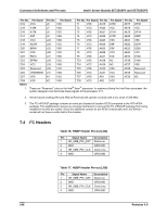 158
158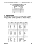 159
159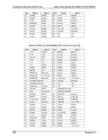 160
160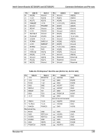 161
161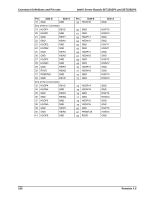 162
162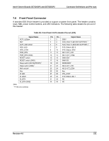 163
163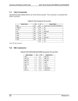 164
164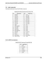 165
165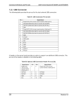 166
166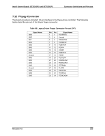 167
167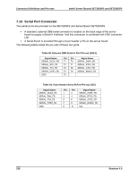 168
168