Intel SE7525GP2 Product Specification - Page 166
USB Connector
 |
View all Intel SE7525GP2 manuals
Add to My Manuals
Save this manual to your list of manuals |
Page 166 highlights
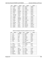
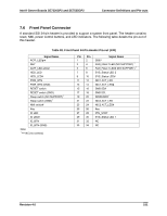
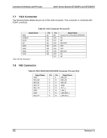
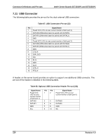
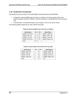
Connector Definitions and Pin-outs Intel® Server Boards SE7320SP2 and SE7525GP2 7.11 USB Connector The following table provides the pin-out for the dual external USB connectors. Table 87. USB Connectors Pin-out (J3) Pin Signal Name 1 Fused VCC (+5V /w over current monitor of both port 3) 2 DATAN3 (Differential data line paired with DATAH3) 3 DATAP3 (Differential data line paired with DATAL3) 4 GND 5 Fused VCC (+5V /w over current monitor of both port 2) 6 DATAN2 (Differential data line paired with DATAH2) 7 DATAP2 (Differential data line paired with DATAL2) 8 GND 9 CTS_N 10 DSR_DCD 11 SIN 12 RI_N 13 GND 14 SIUT 15 DTR_N 16 RTS_N A header on the server board provides an option to support one additional USB connector. The pin-out of the header is detailed in the following table. Table 88. Optional USB Connection Header Pin-out (J31) Signal Name Pin Pin Signal Name Fused VCC 1 2 Fused VCC (+5V /w over (+5V /w over current monitor of both port 0) current monitor of both port 1) DATAN1 3 4 DATAN0 DATAP1 5 6 DATAP0 GND 7 8 GND Key 9 10 NC 154 Revision 4.0
-
 1
1 -
2
-
3
-
4
-
5
-
6
-
7
-
8
-
9
-
10
-
11
-
12
-
13
-
14
-
15
-
16
-
17
-
18
-
19
-
20
-
21
-
22
-
23
-
24
-
25
-
26
-
27
-
28
-
29
-
30
-
31
-
32
-
33
-
34
-
35
-
36
-
37
-
38
-
39
-
40
-
41
-
42
-
43
-
44
-
45
-
46
-
47
-
48
-
49
-
50
-
51
-
52
-
53
-
54
-
55
-
56
-
57
-
58
-
59
-
60
-
61
-
62
-
63
-
64
-
65
-
66
-
67
-
68
-
69
-
70
-
71
-
72
-
73
-
74
-
75
-
76
-
77
-
78
-
79
-
80
-
81
-
82
-
83
-
84
-
85
-
86
-
87
-
88
-
89
-
90
-
91
-
92
-
93
-
94
-
95
-
96
-
97
-
98
-
99
-
100
-
101
-
102
-
103
-
104
-
105
-
106
-
107
-
108
-
109
-
110
-
111
-
112
-
113
-
114
-
115
-
116
-
117
-
118
-
119
-
120
-
121
-
122
-
123
-
124
-
125
-
126
-
127
-
128
-
129
-
130
-
131
-
132
-
133
-
134
-
135
-
136
-
137
-
138
-
139
-
140
-
141
-
142
-
143
-
144
-
145
-
146
-
147
-
148
-
149
-
150
-
151
-
152
-
153
-
154
-
155
-
156
-
157
-
158
-
159
-
160
-
 161
161 -
 162
162 -
 163
163 -
 164
164 -
 165
165 -
 166
166 -
 167
167 -
 168
168 -
 169
169 -
 170
170 -
 171
171 -
172
-
173
-
174
-
175
-
176
-
177
-
178
-
179
-
180
-
181
-
182
-
183
-
184
 |
 |