Intel SE7525GP2 Product Specification - Page 173
General Specifications
 |
View all Intel SE7525GP2 manuals
Add to My Manuals
Save this manual to your list of manuals |
Page 173 highlights
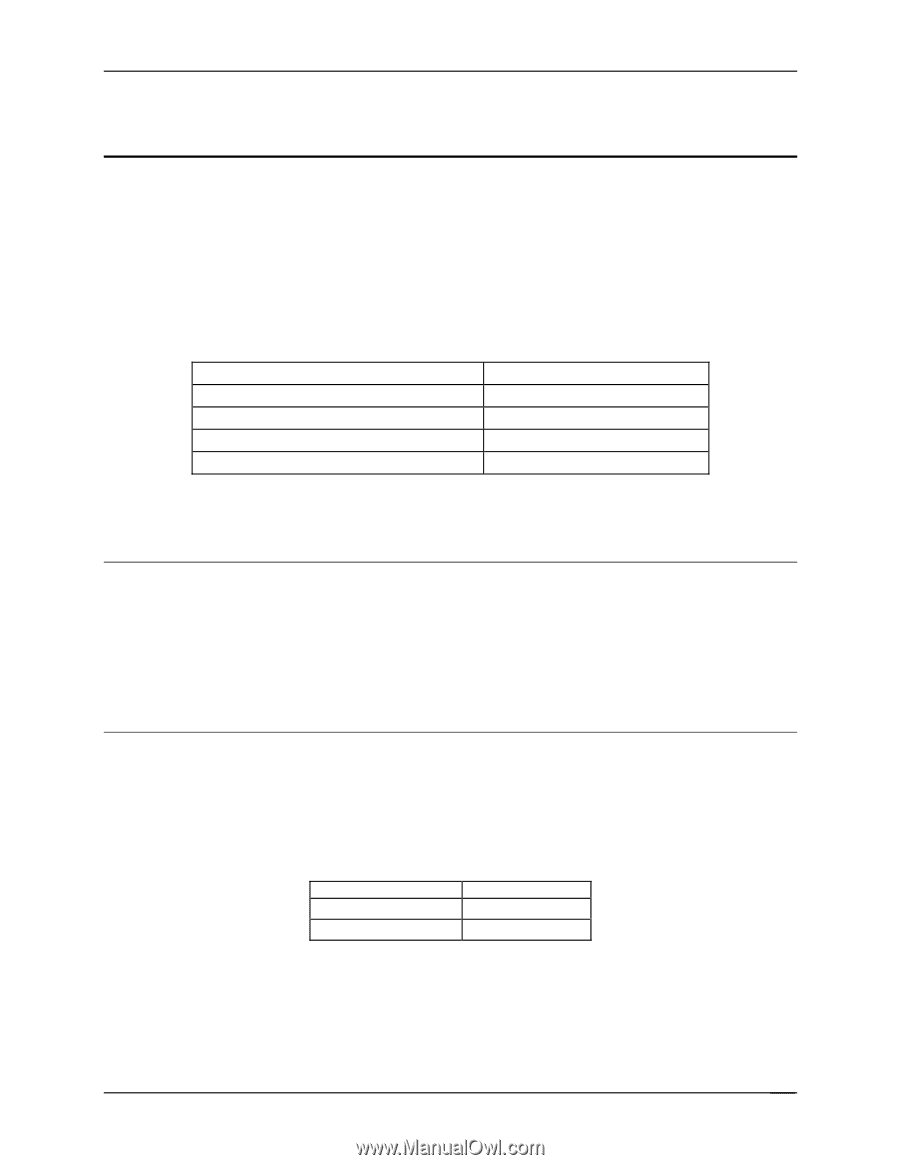
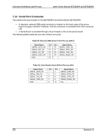
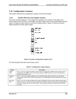
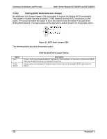
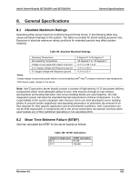
Intel® Server Boards SE7320SP2 and SE7525GP2 General Specifications 8. General Specifications 8.1 Absolute Maximum Ratings Operating either server board at conditions beyond those shown in the following table may cause permanent damage to the system. The table is provided for stress testing purposes only. Exposure to absolute maximum rating conditions for extended periods may affect system reliability. Table 99. Absolute Maximum Ratings Operating Temperature 0 degrees C to 55 degrees C Non-operating Temperature -40 degrees C to +70 degrees C Voltage on any signal with respect to ground -0.3 V to Vdd + 0.3V 3.3 V Supply Voltage with Respect to ground -0.3 V to 3.63 V 5 V Supply Voltage with Respect to ground -0.3 V to 5.5 V Notes: Chassis design must provide proper airflow to avoid exceeding Intel® Xeon® processor maximum case temperature. VDD means supply voltage for the device Note: Intel Corporation server boards contain a number of high-density VLSI and power delivery components which need adequate airflow to cool. Intel ensures through its own chassis development and testing that when Intel server building blocks are used together, the fully integrated system will meet the intended thermal requirements of these components. It is the responsibility of the system integrator who chooses not to use Intel developed server building blocks to consult vendor datasheets and operating parameters to determine the amount of air flow required for their specific application and environmental conditions. Intel Corporation can not be held responsible, if components fail or the server board does not operate correctly when used outside any of their published operating or non-operating limits. 8.2 Mean Time Between Failure (MTBF) Intel has calculated the MTBF for the server boards as follows: Table 100. MTBF Calculation Ambient Temperature MTBF Calculation 55° C 97,164 40° C 108,598 Revision 4.0 161
-
 1
1 -
2
-
3
-
4
-
5
-
6
-
7
-
8
-
9
-
10
-
11
-
12
-
13
-
14
-
15
-
16
-
17
-
18
-
19
-
20
-
21
-
22
-
23
-
24
-
25
-
26
-
27
-
28
-
29
-
30
-
31
-
32
-
33
-
34
-
35
-
36
-
37
-
38
-
39
-
40
-
41
-
42
-
43
-
44
-
45
-
46
-
47
-
48
-
49
-
50
-
51
-
52
-
53
-
54
-
55
-
56
-
57
-
58
-
59
-
60
-
61
-
62
-
63
-
64
-
65
-
66
-
67
-
68
-
69
-
70
-
71
-
72
-
73
-
74
-
75
-
76
-
77
-
78
-
79
-
80
-
81
-
82
-
83
-
84
-
85
-
86
-
87
-
88
-
89
-
90
-
91
-
92
-
93
-
94
-
95
-
96
-
97
-
98
-
99
-
100
-
101
-
102
-
103
-
104
-
105
-
106
-
107
-
108
-
109
-
110
-
111
-
112
-
113
-
114
-
115
-
116
-
117
-
118
-
119
-
120
-
121
-
122
-
123
-
124
-
125
-
126
-
127
-
128
-
129
-
130
-
131
-
132
-
133
-
134
-
135
-
136
-
137
-
138
-
139
-
140
-
141
-
142
-
143
-
144
-
145
-
146
-
147
-
148
-
149
-
150
-
151
-
152
-
153
-
154
-
155
-
156
-
157
-
158
-
159
-
160
-
161
-
162
-
163
-
164
-
165
-
166
-
167
-
 168
168 -
 169
169 -
 170
170 -
 171
171 -
 172
172 -
 173
173 -
 174
174 -
 175
175 -
 176
176 -
 177
177 -
 178
178 -
179
-
180
-
181
-
182
-
183
-
184
 |
 |