Intel SE7525GP2 Product Specification - Page 51
Network Interface Controller NIC
 |
View all Intel SE7525GP2 manuals
Add to My Manuals
Save this manual to your list of manuals |
Page 51 highlights
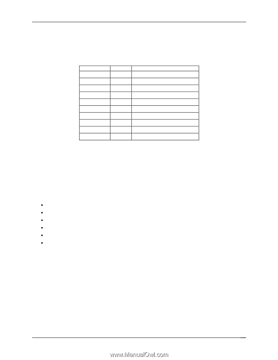
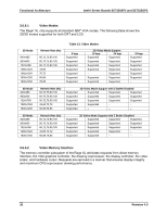
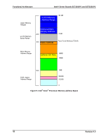
Intel® Server Boards SE7320SP2 and SE7525GP2 Functional Architecture The server boards support an 8-MB (512 KB x 32-bit x four banks) SDRAM device for video memory. The following table shows the video memory interface signals: Table 14. Video Memory Interface Signal Name CAS# CKE CS#[1..0] DQM[7..0] DSF HCLK [11..0] MD[31..0] RAS# WE# I/O Type O O O O O O O I/O O O Description Column Address Select Clock Enable for Memory Chip Select for Memory Memory Data Byte Mask Memory Special Function Enable Memory Clock Memory Address Bus Memory Data Bus Row Address Select Write Enable 3.6.7 Network Interface Controller (NIC) 3.6.7.1 Intel® 82541 The Intel® 82541 gigabit network interface controller supplies the server board with a single network interface. The 82541 controller is capable of supporting 10/100/1000 operation and alert-on-LAN functionality. The controller can be disabled by using the BIOS Setup Utility accessed during POST. The 82541 supports the following features: ƒ 32-bit PCI Rev. 2.3 compliant master interface ƒ Integrated IEEE 802.3 10Base-T, 100Base-TX and 1000Base-TX compatible PHY ƒ IEEE 820.3ab auto-negotiation support ƒ Full duplex support at 10 Mbps, 100Mbps and 1000 Mbps operation ƒ Integrated UNDI ROM support ƒ MDI/MDI-X and HWI support 3.6.7.2 NIC Connector and Status LEDs The Intel® 82541 network controller drives two LEDs located on the network interface connector. The link/activity LED (to the left of the connector) indicates network connection when on, and Transmit/Receive activity when blinking. The speed LED (to the right of the connector) indicates 1000-Mbps operations when amber, 100-Mbps operations when green, and 10-Mbps when off. Revision 4.0 39
-
 1
1 -
2
-
3
-
4
-
5
-
6
-
7
-
8
-
9
-
10
-
11
-
12
-
13
-
14
-
15
-
16
-
17
-
18
-
19
-
20
-
21
-
22
-
23
-
24
-
25
-
26
-
27
-
28
-
29
-
30
-
31
-
32
-
33
-
34
-
35
-
36
-
37
-
38
-
39
-
40
-
41
-
42
-
43
-
44
-
45
-
 46
46 -
 47
47 -
 48
48 -
 49
49 -
 50
50 -
 51
51 -
 52
52 -
 53
53 -
 54
54 -
 55
55 -
 56
56 -
57
-
58
-
59
-
60
-
61
-
62
-
63
-
64
-
65
-
66
-
67
-
68
-
69
-
70
-
71
-
72
-
73
-
74
-
75
-
76
-
77
-
78
-
79
-
80
-
81
-
82
-
83
-
84
-
85
-
86
-
87
-
88
-
89
-
90
-
91
-
92
-
93
-
94
-
95
-
96
-
97
-
98
-
99
-
100
-
101
-
102
-
103
-
104
-
105
-
106
-
107
-
108
-
109
-
110
-
111
-
112
-
113
-
114
-
115
-
116
-
117
-
118
-
119
-
120
-
121
-
122
-
123
-
124
-
125
-
126
-
127
-
128
-
129
-
130
-
131
-
132
-
133
-
134
-
135
-
136
-
137
-
138
-
139
-
140
-
141
-
142
-
143
-
144
-
145
-
146
-
147
-
148
-
149
-
150
-
151
-
152
-
153
-
154
-
155
-
156
-
157
-
158
-
159
-
160
-
161
-
162
-
163
-
164
-
165
-
166
-
167
-
168
-
169
-
170
-
171
-
172
-
173
-
174
-
175
-
176
-
177
-
178
-
179
-
180
-
181
-
182
-
183
-
184
 |
 |