Intel SE7525GP2 Product Specification - Page 174
Processor Power Support, Power Supply Specifications
 |
View all Intel SE7525GP2 manuals
Add to My Manuals
Save this manual to your list of manuals |
Page 174 highlights
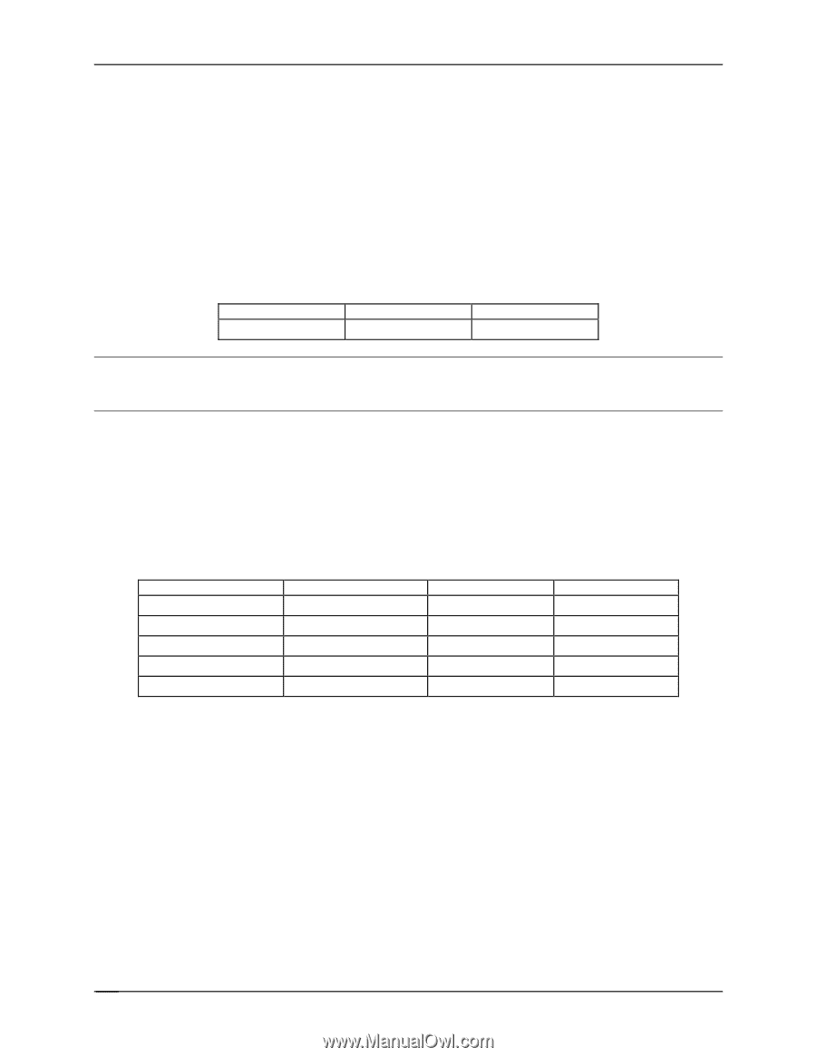
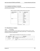
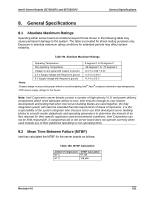
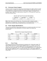
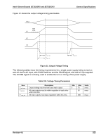
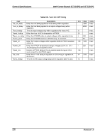
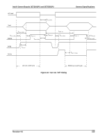
General Specifications Intel® Server Boards SE7320SP2 and SE7525GP2 8.3 Processor Power Support The server boards are designed to support the Thermal Design Point (TDP) guideline for Intel® Xeon® processors. In addition, the Flexible Motherboard Guidelines (FMB) have been followed to help determine the suggested thermal and current design values for anticipating future processor needs. Table 101 provides maximum values for Icc, TDP power and TCASE for the Intel Xeon processor family. Table 101. Intel® Xeon® Processor DP TDP Guidelines TDP Power 103 W Max TCASE 72º C Icc MAX 92 A Note: These values are for reference only. The processor EMTS contains the actual specifications for the processor. If the values found in the EMTS are different then those published here, the EMTS values will supersede these, and should be used. 8.4 Power Supply Specifications This section provides power supply design guidelines for an system using either server board, including voltage and current specifications, and power supply on/off sequencing characteristics. Output +3.3 V +5 V +12 V -12 V +5 V SB Table 102. Power Supply Voltage Specification Min 3.14 V 4.75 V 11.40 V -11.40 V 4.75 V Max 3.46 V 5.25 V 12.60 V -13.08 V 5.25 V Tolerance +5 / -5 % +5 / -5 % +5 / -5% +5 / -9 % +5/ -5% 8.4.1 Power Timing This section discusses the timing requirements for operation with a single power supply. The output voltages must rise from 10% to within regulation limits (Tvout_rise) within 5 ms to 70 ms. The +3.3 V, +5 V and +12 V output voltages start to rise approximately at the same time. All outputs must rise monotonically. The +5 V output must be greater than the +3.3 V output during any point of the voltage rise, however, never by more than 2.25 V. Each output voltage shall reach regulation within 50 ms (Tvout_on) of each other and begin to turn off within 400 ms (Tvout_off) of each other. 162 Revision 4.0
-
 1
1 -
2
-
3
-
4
-
5
-
6
-
7
-
8
-
9
-
10
-
11
-
12
-
13
-
14
-
15
-
16
-
17
-
18
-
19
-
20
-
21
-
22
-
23
-
24
-
25
-
26
-
27
-
28
-
29
-
30
-
31
-
32
-
33
-
34
-
35
-
36
-
37
-
38
-
39
-
40
-
41
-
42
-
43
-
44
-
45
-
46
-
47
-
48
-
49
-
50
-
51
-
52
-
53
-
54
-
55
-
56
-
57
-
58
-
59
-
60
-
61
-
62
-
63
-
64
-
65
-
66
-
67
-
68
-
69
-
70
-
71
-
72
-
73
-
74
-
75
-
76
-
77
-
78
-
79
-
80
-
81
-
82
-
83
-
84
-
85
-
86
-
87
-
88
-
89
-
90
-
91
-
92
-
93
-
94
-
95
-
96
-
97
-
98
-
99
-
100
-
101
-
102
-
103
-
104
-
105
-
106
-
107
-
108
-
109
-
110
-
111
-
112
-
113
-
114
-
115
-
116
-
117
-
118
-
119
-
120
-
121
-
122
-
123
-
124
-
125
-
126
-
127
-
128
-
129
-
130
-
131
-
132
-
133
-
134
-
135
-
136
-
137
-
138
-
139
-
140
-
141
-
142
-
143
-
144
-
145
-
146
-
147
-
148
-
149
-
150
-
151
-
152
-
153
-
154
-
155
-
156
-
157
-
158
-
159
-
160
-
161
-
162
-
163
-
164
-
165
-
166
-
167
-
168
-
 169
169 -
 170
170 -
 171
171 -
 172
172 -
 173
173 -
 174
174 -
 175
175 -
 176
176 -
 177
177 -
 178
178 -
 179
179 -
180
-
181
-
182
-
183
-
184
 |
 |