Intel SE7525GP2 Product Specification - Page 171
Configuration Jumpers
 |
View all Intel SE7525GP2 manuals
Add to My Manuals
Save this manual to your list of manuals |
Page 171 highlights
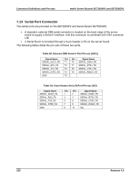
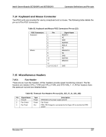
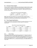
Intel® Server Boards SE7320SP2 and SE7525GP2 Connector Definitions and Pin-outs 7.16 Configuration Jumpers This section describes the configuration jumpers on the server boards. 7.16.1 System Recovery and Update Jumpers The server boards provide an 11-pin single inline header (J17), located on the edge of the server board next to PCI Slot 1, this header provides a total of three 3-pin jumper blocks that are used to configure several system recovery and update options. Figure 19 shows the factory default locations for each jumper option. Figure 19. System Configuration Jumpers (J17) The following table describes each jumper option. Option CMOS Clear Password Clear Recovery Boot Table 97. Configuration Jumper Options Description If pins 1 and 2 are jumpered (default), preservation of configuration CMOS through system reset is controlled by the mBMC. If pins 2 and 3 are jumpered, CMOS contents are set to manufacturing default during system reset. If pins 1 and 2 are jumpered (default), the current BIOS Setup Utility passwords are maintained during system reset. If pins 2 and 3 are jumpered, the Administrator and user passwords are cleared on reset. If pins 1 and 2 are jumpered (default) the system will attempt to boot using the BIOS programmed in the Flash memory. If pins 2 and 3 are jumpered, the BIOS will attempt a recovery boot, loading BIOS code from a floppy disk into the Flash device. This is typically used when the BIOS code has been corrupted. Revision 4.0 159
-
 1
1 -
2
-
3
-
4
-
5
-
6
-
7
-
8
-
9
-
10
-
11
-
12
-
13
-
14
-
15
-
16
-
17
-
18
-
19
-
20
-
21
-
22
-
23
-
24
-
25
-
26
-
27
-
28
-
29
-
30
-
31
-
32
-
33
-
34
-
35
-
36
-
37
-
38
-
39
-
40
-
41
-
42
-
43
-
44
-
45
-
46
-
47
-
48
-
49
-
50
-
51
-
52
-
53
-
54
-
55
-
56
-
57
-
58
-
59
-
60
-
61
-
62
-
63
-
64
-
65
-
66
-
67
-
68
-
69
-
70
-
71
-
72
-
73
-
74
-
75
-
76
-
77
-
78
-
79
-
80
-
81
-
82
-
83
-
84
-
85
-
86
-
87
-
88
-
89
-
90
-
91
-
92
-
93
-
94
-
95
-
96
-
97
-
98
-
99
-
100
-
101
-
102
-
103
-
104
-
105
-
106
-
107
-
108
-
109
-
110
-
111
-
112
-
113
-
114
-
115
-
116
-
117
-
118
-
119
-
120
-
121
-
122
-
123
-
124
-
125
-
126
-
127
-
128
-
129
-
130
-
131
-
132
-
133
-
134
-
135
-
136
-
137
-
138
-
139
-
140
-
141
-
142
-
143
-
144
-
145
-
146
-
147
-
148
-
149
-
150
-
151
-
152
-
153
-
154
-
155
-
156
-
157
-
158
-
159
-
160
-
161
-
162
-
163
-
164
-
165
-
 166
166 -
 167
167 -
 168
168 -
 169
169 -
 170
170 -
 171
171 -
 172
172 -
 173
173 -
 174
174 -
 175
175 -
 176
176 -
177
-
178
-
179
-
180
-
181
-
182
-
183
-
184
 |
 |