Intel SE7525GP2 Product Specification - Page 130
Status/Fault LED, Critical Condition
 |
View all Intel SE7525GP2 manuals
Add to My Manuals
Save this manual to your list of manuals |
Page 130 highlights
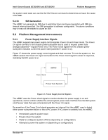
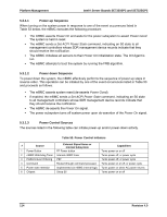
Platform Management Intel® Server Boards SE7320SP2 and SE7525GP2 ƒ The Chassis Identify Push-button works using a "push-on/push-off" operation. Each press of the push-button toggles the LED signal state between on and off. If the pushbutton is used to turn the LED on, it will stay on indefinitely, until either the button is pressed again or a Chassis Identify or Chassis Identify LED command causes the LED to turn off. Table 55. Chassis ID LEDs Color Blue Condition Off Blink When Ok Identify button pressed or Chassis Identify command executed 5.3.4.5 Status/Fault LED The following table shows mapping of sensors/faults to the LED state. Table 56. Fault/Status LED Color Green Amber Off Condition Solid Blink Solid Blink Solid System Ready When System Ready, but degraded. CPU fault, DIMM killed Critical Failure: critical fan, voltage, temperature state Non-Critical Failure: non-critical fan, voltage, temperature state Not Ready. POST error/NMI event/CPU or terminator missing Critical Condition Any critical or non-recoverable threshold crossing associated with the following events: ƒ Temperature, voltage, or fan critical threshold crossing. ƒ Power subsystem failure. The BMC asserts this failure whenever it detects a power control fault (e.g., the BMC detects that the system power is remaining on even though the BMC has deasserted the signal to turn off power to the system). A hot-swap backplane would use the Set Fault Indication command to indicate when one or more of the drive fault status LEDs are asserted on the hot-swap backplane. ƒ The system is unable to power up due to incorrectly installed processor(s), or processor incompatibility. ƒ Satellite controller sends a critical or non-recoverable state, via the Set Fault Indication command to the BMC. ƒ "Critical Event Logging" errors, including: System Memory Uncorrectable ECC error and Fatal/Uncorrectable Bus errors, such as PCI SERR and PERR. 118 Revision 4.0
-
 1
1 -
2
-
3
-
4
-
5
-
6
-
7
-
8
-
9
-
10
-
11
-
12
-
13
-
14
-
15
-
16
-
17
-
18
-
19
-
20
-
21
-
22
-
23
-
24
-
25
-
26
-
27
-
28
-
29
-
30
-
31
-
32
-
33
-
34
-
35
-
36
-
37
-
38
-
39
-
40
-
41
-
42
-
43
-
44
-
45
-
46
-
47
-
48
-
49
-
50
-
51
-
52
-
53
-
54
-
55
-
56
-
57
-
58
-
59
-
60
-
61
-
62
-
63
-
64
-
65
-
66
-
67
-
68
-
69
-
70
-
71
-
72
-
73
-
74
-
75
-
76
-
77
-
78
-
79
-
80
-
81
-
82
-
83
-
84
-
85
-
86
-
87
-
88
-
89
-
90
-
91
-
92
-
93
-
94
-
95
-
96
-
97
-
98
-
99
-
100
-
101
-
102
-
103
-
104
-
105
-
106
-
107
-
108
-
109
-
110
-
111
-
112
-
113
-
114
-
115
-
116
-
117
-
118
-
119
-
120
-
121
-
122
-
123
-
124
-
 125
125 -
 126
126 -
 127
127 -
 128
128 -
 129
129 -
 130
130 -
 131
131 -
 132
132 -
 133
133 -
 134
134 -
 135
135 -
136
-
137
-
138
-
139
-
140
-
141
-
142
-
143
-
144
-
145
-
146
-
147
-
148
-
149
-
150
-
151
-
152
-
153
-
154
-
155
-
156
-
157
-
158
-
159
-
160
-
161
-
162
-
163
-
164
-
165
-
166
-
167
-
168
-
169
-
170
-
171
-
172
-
173
-
174
-
175
-
176
-
177
-
178
-
179
-
180
-
181
-
182
-
183
-
184
 |
 |