Intel SE7525GP2 Product Specification - Page 139
Processor Bus Error, 1.2.3, Memory Bus Error, 1.2.4, System Limit Error, 1.2.5, Processor
 |
View all Intel SE7525GP2 manuals
Add to My Manuals
Save this manual to your list of manuals |
Page 139 highlights
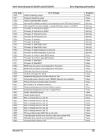
Intel® Server Boards SE7320SP2 and SE7525GP2 Error Reporting and Handling PERR# and SERR# through NMI. Disabling NMI for PERR# and/or SERR# also disables logging of the corresponding event. In the case of PERR#, the PCI bus master has the option to retry the offending transaction, or to report it using SERR#. All other PCI-related errors are reported by SERR#. All the PCI-to-PCI bridges are configured so that they generate a SERR# on the primary interface whenever there is a SERR# on the secondary side, if SERR# has been enabled through Setup. The same is true for PERR#. 6.1.2.2 Processor Bus Error If the chipset supports ECC on the processor bus then the BIOS enables the error correction and detection capabilities of the processors by setting appropriate bits in the processor model specific register (MSR) and appropriate bits inside the chipset. In the case of irrecoverable errors on the host processor bus, proper execution of the asynchronous error handler (usually SMI) cannot be guaranteed and the handler cannot be relied upon to log such conditions. The handler will record the error to the SEL only if the system has not experienced a catastrophic failure that compromises the integrity of the handler. 6.1.2.3 Memory Bus Error The hardware is programmed to generate an SMI on single-bit data errors in the memory array if ECC memory is installed. The SMI handler records the error and the DIMM location to the system event log. Double-bit errors in the memory array are mapped to the SMI because the mBMC cannot determine the location of the bad DIMM. The double-bit errors may have corrupted the contents of SMRAM. The SMI handler will log the failing DIMM number to the mBMC if the SMRAM contents are still valid. The ability to isolate the failure down to a single DIMM may not be available on certain platforms, and/or during early POST. 6.1.2.4 System Limit Error The BMC monitors system operational limits. It manages the A/D converter, defining voltage and temperature limits as well as fan sensors and chassis intrusion. Any sensor values outside of specified limits are fully handled by the mBMC. The BIOS does not generate an SMI to the host processor for these types of system events. 6.1.2.5 Processor Failure The BIOS detects any processor BIST failures and logs the event. The failed processor can be identified by the first OEM data byte field in the log. For example, if processor 0 fails, the first OEM data byte will be 0. The BIOS depends upon the mBMC to log the watchdog timer reset event. If an operating system device driver is using the watchdog timer to detect software or hardware failures and that timer expires, an Asynchronous Reset (ASR) is generated, which is equivalent to a hard reset. The POST portion of the BIOS can query the mBMC for a watchdog reset event as the system reboots, and then log this event in the SEL. Revision 4.0 127
-
 1
1 -
2
-
3
-
4
-
5
-
6
-
7
-
8
-
9
-
10
-
11
-
12
-
13
-
14
-
15
-
16
-
17
-
18
-
19
-
20
-
21
-
22
-
23
-
24
-
25
-
26
-
27
-
28
-
29
-
30
-
31
-
32
-
33
-
34
-
35
-
36
-
37
-
38
-
39
-
40
-
41
-
42
-
43
-
44
-
45
-
46
-
47
-
48
-
49
-
50
-
51
-
52
-
53
-
54
-
55
-
56
-
57
-
58
-
59
-
60
-
61
-
62
-
63
-
64
-
65
-
66
-
67
-
68
-
69
-
70
-
71
-
72
-
73
-
74
-
75
-
76
-
77
-
78
-
79
-
80
-
81
-
82
-
83
-
84
-
85
-
86
-
87
-
88
-
89
-
90
-
91
-
92
-
93
-
94
-
95
-
96
-
97
-
98
-
99
-
100
-
101
-
102
-
103
-
104
-
105
-
106
-
107
-
108
-
109
-
110
-
111
-
112
-
113
-
114
-
115
-
116
-
117
-
118
-
119
-
120
-
121
-
122
-
123
-
124
-
125
-
126
-
127
-
128
-
129
-
130
-
131
-
132
-
133
-
 134
134 -
 135
135 -
 136
136 -
 137
137 -
 138
138 -
 139
139 -
 140
140 -
 141
141 -
 142
142 -
 143
143 -
 144
144 -
145
-
146
-
147
-
148
-
149
-
150
-
151
-
152
-
153
-
154
-
155
-
156
-
157
-
158
-
159
-
160
-
161
-
162
-
163
-
164
-
165
-
166
-
167
-
168
-
169
-
170
-
171
-
172
-
173
-
174
-
175
-
176
-
177
-
178
-
179
-
180
-
181
-
182
-
183
-
184
 |
 |