Intel SE7525GP2 Product Specification - Page 37
Table 5. Supported DDR-333 DIMM Populations - virtualization support
 |
View all Intel SE7525GP2 manuals
Add to My Manuals
Save this manual to your list of manuals |
Page 37 highlights
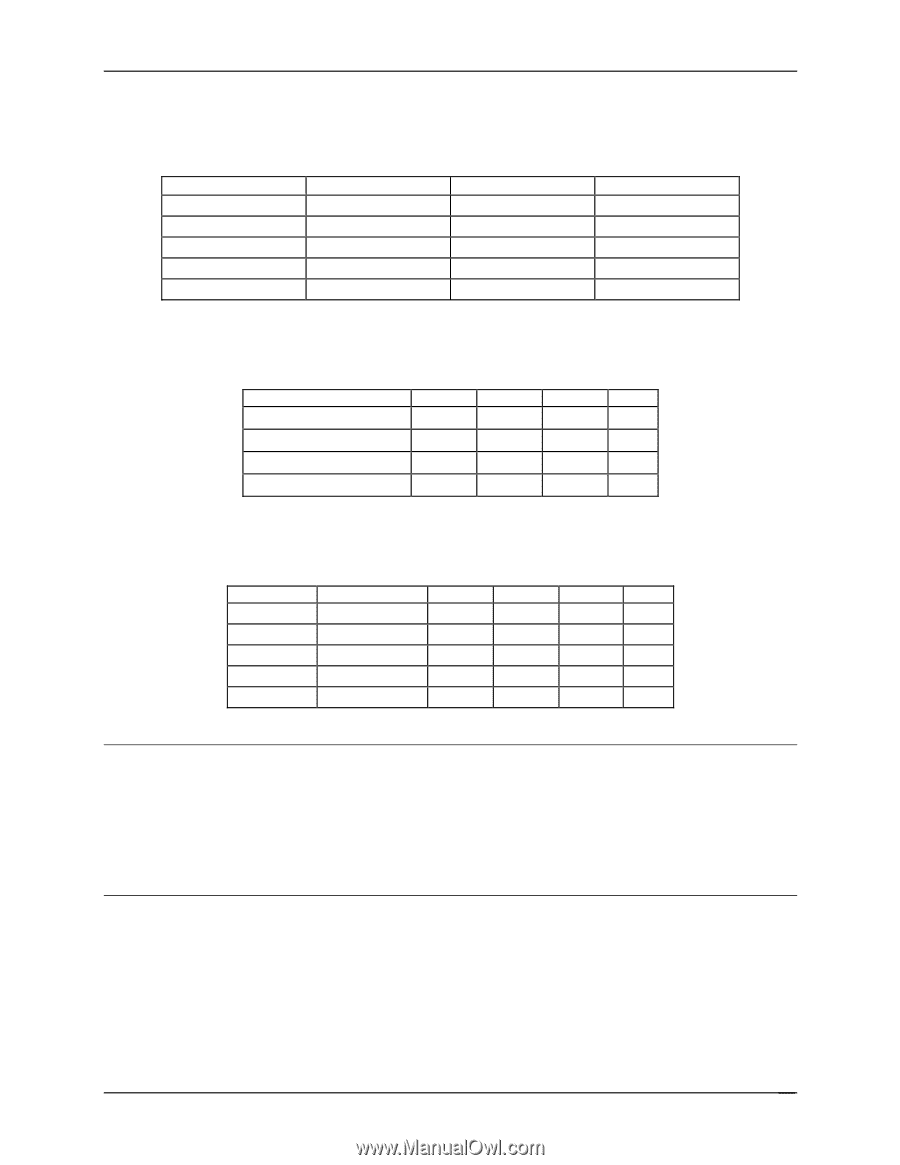
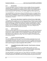
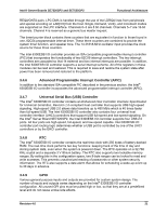
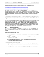
Intel® Server Boards SE7320SP2 and SE7525GP2 Functional Architecture Table 5. Supported DDR-333 DIMM Populations DIMM Slot A2 E S/R E D/R D/R DIMM Slot A1 S/R S/R D/R D/R S/R DIMM Slot B2 E E E E E DIMM Slot B1 E E E E E Table 6. DIMM Module Capacities Parts X8, single row X8, double row X4, single row X4, Stacked, double row 128Mb 256 MB 256 MB 512 MB 256Mb 256 MB 512 MB 512 MB 1 GB 512Mb 512 MB 1 GB 1 GB 2 GB 1Gb 1 GB 2 GB 2 GB 4 GB Table 7. Possible Memory Capacities # of DIMMS 1 2 2 4 4 Spare Single Channel X X 128 Mb 256 MB 512 MB 1 GB 1 GB 2 GB 256 Mb 512 MB 1 GB 2 GB 2 GB 4 GB 512 Mb 1 GB 2 GB 4 GB 4 GB 8 GB 1 Gb 2 GB 4 GB 8 GB 8 GB Note: Memory between 4 GB and 4 GB minus 512 MB is not be accessible for use by the operating system and may be lost to the user. This area is reserved for BIOS, APIC configuration space, PCI adapter interface, and virtual video memory space. This means that if 4 GB of memory is installed, 3.5 GB of this memory is usable. The chipset should allow the remapping of unused memory above the 4 GB address, but this memory may not be accessible to an operating system that has a 4 GB memory limit. The minimum memory installed is 256 MB (one 256 MB DIMM). 3.5.3 I2C Bus To boot the system, the system BIOS uses a dedicated I2C bus to retrieve DIMM information needed to program the MCH memory registers. Revision 4.0 25
-
 1
1 -
2
-
3
-
4
-
5
-
6
-
7
-
8
-
9
-
10
-
11
-
12
-
13
-
14
-
15
-
16
-
17
-
18
-
19
-
20
-
21
-
22
-
23
-
24
-
25
-
26
-
27
-
28
-
29
-
30
-
31
-
 32
32 -
 33
33 -
 34
34 -
 35
35 -
 36
36 -
 37
37 -
 38
38 -
 39
39 -
 40
40 -
 41
41 -
 42
42 -
43
-
44
-
45
-
46
-
47
-
48
-
49
-
50
-
51
-
52
-
53
-
54
-
55
-
56
-
57
-
58
-
59
-
60
-
61
-
62
-
63
-
64
-
65
-
66
-
67
-
68
-
69
-
70
-
71
-
72
-
73
-
74
-
75
-
76
-
77
-
78
-
79
-
80
-
81
-
82
-
83
-
84
-
85
-
86
-
87
-
88
-
89
-
90
-
91
-
92
-
93
-
94
-
95
-
96
-
97
-
98
-
99
-
100
-
101
-
102
-
103
-
104
-
105
-
106
-
107
-
108
-
109
-
110
-
111
-
112
-
113
-
114
-
115
-
116
-
117
-
118
-
119
-
120
-
121
-
122
-
123
-
124
-
125
-
126
-
127
-
128
-
129
-
130
-
131
-
132
-
133
-
134
-
135
-
136
-
137
-
138
-
139
-
140
-
141
-
142
-
143
-
144
-
145
-
146
-
147
-
148
-
149
-
150
-
151
-
152
-
153
-
154
-
155
-
156
-
157
-
158
-
159
-
160
-
161
-
162
-
163
-
164
-
165
-
166
-
167
-
168
-
169
-
170
-
171
-
172
-
173
-
174
-
175
-
176
-
177
-
178
-
179
-
180
-
181
-
182
-
183
-
184
 |
 |