Intel SE7525GP2 Product Specification - Page 150
Bootblock Recovery Code Checkpoint
 |
View all Intel SE7525GP2 manuals
Add to My Manuals
Save this manual to your list of manuals |
Page 150 highlights
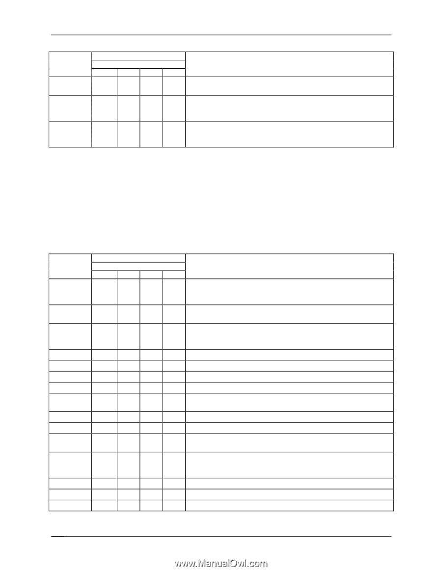
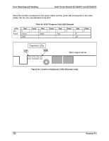
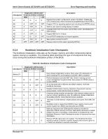
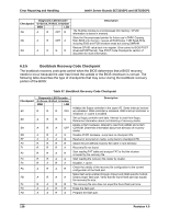
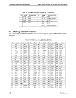
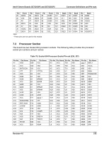
Error Reporting and Handling Intel® Server Boards SE7320SP2 and SE7525GP2 Checkpoint D8 D9 DA Diagnostic LED Decoder G=Green, R=Red, A=Amber MSB LSB A R OFF R A R OFF A A R G R Description The Runtime module is uncompressed into memory. CPUID information is stored in memory. Store the Uncompressed pointer for future use in PMM. Copying Main BIOS into memory. Leaves all RAM below 1 MB Read-Write including E000 and F000 shadow areas but closing SMRAM. Restore CPUID value back into register. Give control to BIOS POST (ExecutePOSTKernel). See POST Code Checkpoints section of document for more information. 6.3.5 Bootblock Recovery Code Checkpoint The bootblock recovery code gets control when the BIOS determines that a BIOS recovery needs to occur because the user has forced the update or the BIOS checksum is corrupt. The following table describes the type of checkpoints that may occur during the bootblock recovery portion of the BIOS: Table 67. Bootblock Recovery Code Checkpoint Checkpoint E0 E9 EA EB EF F0 F1 F2 F3 F5 FA FB F4 FC FD Diagnostic LED Decoder G=Green, R=Red, A=Amber MSB LSB R R R OFF A R R G A R A OFF A R A G A A A G R R R R R R R A R R A R R R A A R A R A A R A R A R A A R A R R A A R R A A R A Description Initialize the floppy controller in the super I/O. Some interrupt vectors are initialized. DMA controller is initialized. 8259 interrupt controller is initialized. L1 cache is enabled. Set up floppy controller and data. Attempt to read from floppy. Determine information about root directory of recovery media. Enable ATAPI hardware. Attempt to read from ARMD and ATAPI CD-ROM. Determine information about root directory of recovery media. Disable ATAPI hardware. Jump back to checkpoint E9. Read error occurred on media. Jump back to checkpoint EB. Search for pre-defined recovery file name in root directory. Recovery file not found. Start reading FAT table and analyze FAT to find the clusters occupied by the recovery file. Start reading the recovery file cluster by cluster. Disable L1 cache. Check the validity of the recovery file configuration to the current configuration of the flash part. Make flash write enabled through chipset and OEM specific method. Detect proper flash part. Verify that the found flash part size equals the recovery file size. The recovery file size does not equal the found flash part size. Erase the flash part. Program the flash part. 138 Revision 4.0
-
 1
1 -
2
-
3
-
4
-
5
-
6
-
7
-
8
-
9
-
10
-
11
-
12
-
13
-
14
-
15
-
16
-
17
-
18
-
19
-
20
-
21
-
22
-
23
-
24
-
25
-
26
-
27
-
28
-
29
-
30
-
31
-
32
-
33
-
34
-
35
-
36
-
37
-
38
-
39
-
40
-
41
-
42
-
43
-
44
-
45
-
46
-
47
-
48
-
49
-
50
-
51
-
52
-
53
-
54
-
55
-
56
-
57
-
58
-
59
-
60
-
61
-
62
-
63
-
64
-
65
-
66
-
67
-
68
-
69
-
70
-
71
-
72
-
73
-
74
-
75
-
76
-
77
-
78
-
79
-
80
-
81
-
82
-
83
-
84
-
85
-
86
-
87
-
88
-
89
-
90
-
91
-
92
-
93
-
94
-
95
-
96
-
97
-
98
-
99
-
100
-
101
-
102
-
103
-
104
-
105
-
106
-
107
-
108
-
109
-
110
-
111
-
112
-
113
-
114
-
115
-
116
-
117
-
118
-
119
-
120
-
121
-
122
-
123
-
124
-
125
-
126
-
127
-
128
-
129
-
130
-
131
-
132
-
133
-
134
-
135
-
136
-
137
-
138
-
139
-
140
-
141
-
142
-
143
-
144
-
 145
145 -
 146
146 -
 147
147 -
 148
148 -
 149
149 -
 150
150 -
 151
151 -
 152
152 -
 153
153 -
 154
154 -
 155
155 -
156
-
157
-
158
-
159
-
160
-
161
-
162
-
163
-
164
-
165
-
166
-
167
-
168
-
169
-
170
-
171
-
172
-
173
-
174
-
175
-
176
-
177
-
178
-
179
-
180
-
181
-
182
-
183
-
184
 |
 |