Konica Minolta AccurioPress C2070/2070P IC-314 User Guide - Page 51
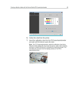
patch in the bottom right corner of the chart circled in red
 |
View all Konica Minolta AccurioPress C2070/2070P manuals
Add to My Manuals
Save this manual to your list of manuals |
Page 51 highlights
Creating calibration tables with the X-Rite i1/iSis/i1iO spectrophotometer 41 12. Use the visor to position the arm of the i1iO spectrophotometer on the color patch in the bottom left corner of the chart (circled in red), and press the i1 measurement button to confirm the position. The next wizard window appears with the patch in the bottom right corner circled in red. 13. Use the visor to position the i1 spectrophotometer on the color patch in the bottom right corner of the chart (circled in red), and press the i1 measurement button to confirm the position. The scanning process starts and the scan progress is shown in the wizard window.
-
 1
1 -
2
-
3
-
4
-
5
-
6
-
7
-
8
-
9
-
10
-
11
-
12
-
13
-
14
-
15
-
16
-
17
-
18
-
19
-
20
-
21
-
22
-
23
-
24
-
25
-
26
-
27
-
28
-
29
-
30
-
31
-
32
-
33
-
34
-
35
-
36
-
37
-
38
-
39
-
40
-
41
-
42
-
43
-
44
-
45
-
 46
46 -
 47
47 -
 48
48 -
 49
49 -
 50
50 -
 51
51 -
 52
52 -
 53
53 -
 54
54 -
 55
55 -
 56
56 -
57
-
58
-
59
-
60
-
61
-
62
-
63
-
64
-
65
-
66
-
67
-
68
-
69
-
70
-
71
-
72
-
73
-
74
-
75
-
76
-
77
-
78
-
79
-
80
-
81
-
82
-
83
-
84
-
85
-
86
-
87
-
88
-
89
-
90
-
91
-
92
-
93
-
94
-
95
-
96
-
97
-
98
-
99
-
100
-
101
-
102
-
103
-
104
-
105
-
106
-
107
-
108
-
109
-
110
-
111
-
112
-
113
-
114
-
115
-
116
-
117
-
118
-
119
-
120
-
121
-
122
-
123
-
124
-
125
-
126
-
127
-
128
-
129
-
130
-
131
-
132
-
133
-
134
-
135
-
136
-
137
-
138
-
139
-
140
-
141
-
142
-
143
-
144
-
145
-
146
-
147
-
148
-
149
-
150
-
151
-
152
-
153
-
154
-
155
-
156
-
157
-
158
-
159
-
160
-
161
-
162
-
163
-
164
-
165
-
166
-
167
-
168
-
169
-
170
-
171
-
172
-
173
-
174
-
175
-
176
-
177
-
178
-
179
-
180
-
181
-
182
-
183
-
184
-
185
-
186
-
187
-
188
-
189
-
190
-
191
-
192
-
193
-
194
-
195
-
196
-
197
-
198
-
199
-
200
-
201
-
202
-
203
-
204
-
205
-
206
-
207
-
208
-
209
-
210
-
211
-
212
-
213
-
214
-
215
-
216
-
217
-
218
-
219
-
220
-
221
-
222
-
223
-
224
-
225
-
226
-
227
-
228
-
229
-
230
-
231
-
232
-
233
-
234
-
235
-
236
-
237
-
238
-
239
-
240
-
241
-
242
-
243
-
244
-
245
-
246
-
247
-
248
-
249
-
250
-
251
-
252
-
253
-
254
-
255
-
256
-
257
-
258
-
259
-
260
-
261
-
262
-
263
-
264
-
265
-
266
-
267
-
268
-
269
-
270
-
271
-
272
-
273
-
274
-
275
-
276
-
277
-
278
-
279
-
280
-
281
 |
 |

12.
Use the visor to position the arm of the i1iO
spectrophotometer on the color patch in the bottom left corner
of the chart (circled in red), and press the i1 measurement
button to confirm the position.
The next wizard window appears with the patch in the bottom
right corner circled in red.
13.
Use the visor to position the i1 spectrophotometer on the color
patch in the bottom right corner of the chart (circled in red),
and press the i1 measurement button to confirm the position.
The scanning process starts and the scan progress is shown
in the wizard window.
Creating calibration tables with the X-Rite i1/iSis/i1iO spectrophotometer
41