Lenovo ThinkPad i Series 1157 ThinkPad 570 User's Reference - Page 21
Rear view of the computer, ThinkPad 570 UltraBase or
 |
View all Lenovo ThinkPad i Series 1157 manuals
Add to My Manuals
Save this manual to your list of manuals |
Page 21 highlights
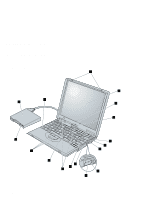
Identifying the hardware features Rear view of the computer 1 The security keyhole is used with a mechanical lock. ( page 156.) 4 The serial connector is where you connect a 9-pin, serial-device cable. 2 The power jack is where the AC Adapter cable is connected. 5 The parallel connector is where you connect a parallel-printer signal cable. 3 The external-diskette-drive connector is where you connect the cable of the external diskette drive. 6 The external-monitor connector is where you attach an external monitor (CRT). 7 The external-input-device connector is used to attach a mouse or an external numeric keypad to the computer. An external keyboard can be attached to this connector through an optional keyboard/mouse cable. 8 The modem connector is used for connecting your computer to a telephone line. Bottom view of the computer 1 The battery pack is a built-in power source for the computer. 2 The battery-pack latch locks or releases the battery pack. 3 The speaker is built in to the computer. 4 The system-expansion connector (244-pin) enables you to connect your computer to a ThinkPad 570 UltraBase or to a ThinkPad 570 Direct Dock Adapter for connection to a port replicator. 5 The fan louvers are for circulating air within the computer. Do not place any object in front of these louvers. 6 The power switch turns the computer on and off. You can slide this switch by pushing the white notch on it. 7 The universal serial bus (USB) connector enables you to connect any device that conforms to the USB interface. Many recent digital devices conform to this new standard. 8 To install or remove the SDRAM dual inline memory module (DIMM) option, loosen this memory-slot-cover screw. 9 The memory slot accepts an SDRAM dual inline memory module (DIMM) option. 1 To install or remove the hard disk, loosen this hard-disk-drive screw. You can use the security screw shipped with your computer as a hard disk screw. 11 The hard disk drive is built in to the computer. 12 The serial number label identifies your computer. You need this number to get help. Chapter 1. Basic information on your computer 5
-
 1
1 -
2
-
3
-
4
-
5
-
6
-
7
-
8
-
9
-
10
-
11
-
12
-
13
-
14
-
15
-
 16
16 -
 17
17 -
 18
18 -
 19
19 -
 20
20 -
 21
21 -
 22
22 -
 23
23 -
 24
24 -
 25
25 -
 26
26 -
27
-
28
-
29
-
30
-
31
-
32
-
33
-
34
-
35
-
36
-
37
-
38
-
39
-
40
-
41
-
42
-
43
-
44
-
45
-
46
-
47
-
48
-
49
-
50
-
51
-
52
-
53
-
54
-
55
-
56
-
57
-
58
-
59
-
60
-
61
-
62
-
63
-
64
-
65
-
66
-
67
-
68
-
69
-
70
-
71
-
72
-
73
-
74
-
75
-
76
-
77
-
78
-
79
-
80
-
81
-
82
-
83
-
84
-
85
-
86
-
87
-
88
-
89
-
90
-
91
-
92
-
93
-
94
-
95
-
96
-
97
-
98
-
99
-
100
-
101
-
102
-
103
-
104
-
105
-
106
-
107
-
108
-
109
-
110
-
111
-
112
-
113
-
114
-
115
-
116
-
117
-
118
-
119
-
120
-
121
-
122
-
123
-
124
-
125
-
126
-
127
-
128
-
129
-
130
-
131
-
132
-
133
-
134
-
135
-
136
-
137
-
138
-
139
-
140
-
141
-
142
-
143
-
144
-
145
-
146
-
147
-
148
-
149
-
150
-
151
-
152
-
153
-
154
-
155
-
156
-
157
-
158
-
159
-
160
-
161
-
162
-
163
-
164
-
165
-
166
-
167
-
168
-
169
-
170
-
171
-
172
-
173
-
174
-
175
-
176
-
177
-
178
-
179
-
180
-
181
-
182
-
183
-
184
-
185
-
186
-
187
-
188
-
189
-
190
-
191
-
192
-
193
-
194
-
195
-
196
-
197
-
198
-
199
-
200
-
201
-
202
-
203
-
204
-
205
-
206
-
207
-
208
-
209
-
210
-
211
-
212
-
213
-
214
-
215
-
216
-
217
-
218
-
219
-
220
-
221
-
222
-
223
-
224
-
225
-
226
-
227
-
228
-
229
-
230
-
231
-
232
-
233
 |
 |