Netgear SRX5308 SRX5308 Reference Manual - Page 64
VLAN DHCP Options, DHCP Server, Check box, Status icon, Profile Name, VLAN ID, Subnet IP, DHCP Status - 2 vpn 2 vlan
 |
UPC - 606449065145
View all Netgear SRX5308 manuals
Add to My Manuals
Save this manual to your list of manuals |
Page 64 highlights
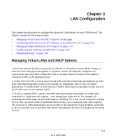
ProSafe Gigabit Quad WAN SSL VPN Firewall SRX5308 Reference Manual For each VLAN profile, the following fields are displayed in the VLAN Profiles table: • Check box. Allows you to select the VLAN profile in the table. • Status icon. Indicates the status of the VLAN profile: - Green circle. The VLAN profile is enabled. - Gray circle. The VLAN profile is disabled. • Profile Name. The unique name assigned to the VLAN profile. • VLAN ID. The unique ID (or tag) assigned to the VLAN profile. • Subnet IP. The subnet IP address for the VLAN profile. • DHCP Status. The DHCP server status for the VLAN profile, which can be either DHCP Enabled or DHCP Disabled. • Action. The Edit table button that provides access to the Edit VLAN Profile screen. 2. Assign a VLAN profile to a LAN port (Port 1, Port 2, Port 3, or Port 4/DMZ) by selecting a VLAN profile from the drop-down list. Both enabled and disabled VLAN profiles are displayed in the drop-down lists. 3. Click Apply to save your settings. Note: For information about how to add and edit a VLAN profile, including its DHCP options, see "Configuring a VLAN Profile" on page 3-6. VLAN DHCP Options For each VLAN, you must specify the Dynamic Host Configuration Protocol (DHCP) options. DHCP Server The default VLAN (VLAN 1) has the DHCP Server option enabled by default, allowing the VPN firewall to assign IP, DNS server, WINS server, and default gateway addresses to all computers connected to the VPN firewall's LAN. The assigned default gateway address is the LAN address of the VPN firewall. IP addresses are assigned to the attached computers from a pool of addresses that you must specify. Each pool address is tested before it is assigned to avoid duplicate addresses on the LAN. When you create a new VLAN, the DHCP server option is disabled by default. For most applications, the default DHCP server and TCP/IP settings of the VPN firewall are satisfactory. Click the link to "Preparing Your Network" in Appendix E for an explanation of DHCP and information about how to assign IP addresses for your network. 3-4 LAN Configuration v1.0, April 2010
-
 1
1 -
2
-
3
-
4
-
5
-
6
-
7
-
8
-
9
-
10
-
11
-
12
-
13
-
14
-
15
-
16
-
17
-
18
-
19
-
20
-
21
-
22
-
23
-
24
-
25
-
26
-
27
-
28
-
29
-
30
-
31
-
32
-
33
-
34
-
35
-
36
-
37
-
38
-
39
-
40
-
41
-
42
-
43
-
44
-
45
-
46
-
47
-
48
-
49
-
50
-
51
-
52
-
53
-
54
-
55
-
56
-
57
-
58
-
 59
59 -
 60
60 -
 61
61 -
 62
62 -
 63
63 -
 64
64 -
 65
65 -
 66
66 -
 67
67 -
 68
68 -
 69
69 -
70
-
71
-
72
-
73
-
74
-
75
-
76
-
77
-
78
-
79
-
80
-
81
-
82
-
83
-
84
-
85
-
86
-
87
-
88
-
89
-
90
-
91
-
92
-
93
-
94
-
95
-
96
-
97
-
98
-
99
-
100
-
101
-
102
-
103
-
104
-
105
-
106
-
107
-
108
-
109
-
110
-
111
-
112
-
113
-
114
-
115
-
116
-
117
-
118
-
119
-
120
-
121
-
122
-
123
-
124
-
125
-
126
-
127
-
128
-
129
-
130
-
131
-
132
-
133
-
134
-
135
-
136
-
137
-
138
-
139
-
140
-
141
-
142
-
143
-
144
-
145
-
146
-
147
-
148
-
149
-
150
-
151
-
152
-
153
-
154
-
155
-
156
-
157
-
158
-
159
-
160
-
161
-
162
-
163
-
164
-
165
-
166
-
167
-
168
-
169
-
170
-
171
-
172
-
173
-
174
-
175
-
176
-
177
-
178
-
179
-
180
-
181
-
182
-
183
-
184
-
185
-
186
-
187
-
188
-
189
-
190
-
191
-
192
-
193
-
194
-
195
-
196
-
197
-
198
-
199
-
200
-
201
-
202
-
203
-
204
-
205
-
206
-
207
-
208
-
209
-
210
-
211
-
212
-
213
-
214
-
215
-
216
-
217
-
218
-
219
-
220
-
221
-
222
-
223
-
224
-
225
-
226
-
227
-
228
-
229
-
230
-
231
-
232
-
233
-
234
-
235
-
236
-
237
-
238
-
239
-
240
-
241
-
242
-
243
-
244
-
245
-
246
-
247
-
248
-
249
-
250
-
251
-
252
-
253
-
254
-
255
-
256
-
257
-
258
-
259
-
260
-
261
-
262
-
263
-
264
-
265
-
266
-
267
-
268
-
269
-
270
-
271
-
272
-
273
-
274
-
275
-
276
-
277
-
278
-
279
-
280
-
281
-
282
-
283
-
284
-
285
-
286
-
287
-
288
-
289
-
290
-
291
-
292
-
293
-
294
-
295
-
296
-
297
-
298
-
299
-
300
-
301
-
302
-
303
-
304
-
305
-
306
-
307
-
308
-
309
-
310
-
311
-
312
-
313
-
314
-
315
-
316
-
317
-
318
-
319
-
320
-
321
-
322
-
323
-
324
-
325
-
326
-
327
-
328
-
329
-
330
-
331
-
332
-
333
-
334
-
335
-
336
-
337
-
338
-
339
-
340
-
341
-
342
-
343
-
344
-
345
-
346
-
347
-
348
-
349
-
350
-
351
-
352
-
353
-
354
-
355
-
356
-
357
-
358
-
359
-
360
-
361
-
362
-
363
-
364
-
365
-
366
-
367
-
368
-
369
-
370
-
371
-
372
-
373
-
374
-
375
-
376
-
377
-
378
-
379
-
380
-
381
-
382
-
383
-
384
 |
 |
