Dell PowerEdge T300 Hardware Owner's Manual (PDF) - Page 104
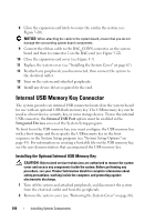
Internal USB Memory Key Connector, Installing the Optional Internal USB Memory Key - boot from usb
 |
View all Dell PowerEdge T300 manuals
Add to My Manuals
Save this manual to your list of manuals |
Page 104 highlights
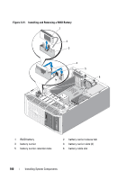
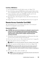
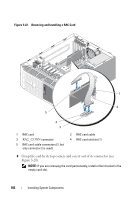
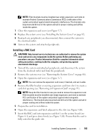
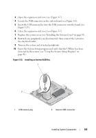
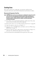
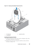
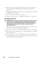
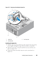
8 Close the expansion card latch to secure the card in the system (see Figure 3-20). NOTICE: When attaching the cable to the system board, ensure that you do not damage the surrounding system board components. 9 Connect the ribbon cable to the RAC_CONN connector on the system board and then to connector 2 on the RAC card (see Figure 3-22). 10 Close the expansion card cover (see Figure 3-7). 11 Replace the system cover (see "Installing the System Cover" on page 67). 12 Reattach any peripherals you disconnected, then connect the system to the electrical outlet. 13 Turn on the system and attached peripherals. 14 Install any device drivers required for the card. Internal USB Memory Key Connector The system provides an internal USB connector located on the system board for use with an optional USB flash memory key. The USB memory key can be used as a boot device, security key, or mass storage device. To use the internal USB connector, the Internal USB Port option must be enabled in the Integrated Devices screen of the System Setup program. To boot from the USB memory key, you must configure the USB memory key with a boot image and then specify the USB memory key in the boot sequence in the System Setup program (see "System Setup Options" on page 43). For information on creating a bootable file on the USB memory key, see the user documentation that accompanied the USB memory key. Installing the Optional Internal USB Memory Key CAUTION: Only trained service technicians are authorized to remove the system cover and access any components inside the system. Before performing any procedure, see your Product Information Guide for complete information about safety precautions, working inside the computer, and protecting against electrostatic discharge. 1 Turn off the system and attached peripherals, and disconnect the system from the electrical outlet and from the peripherals. 2 Remove the system cover (see "Removing the System Cover" on page 66). 104 Installing System Components
-
 1
1 -
2
-
3
-
4
-
5
-
6
-
7
-
8
-
9
-
10
-
11
-
12
-
13
-
14
-
15
-
16
-
17
-
18
-
19
-
20
-
21
-
22
-
23
-
24
-
25
-
26
-
27
-
28
-
29
-
30
-
31
-
32
-
33
-
34
-
35
-
36
-
37
-
38
-
39
-
40
-
41
-
42
-
43
-
44
-
45
-
46
-
47
-
48
-
49
-
50
-
51
-
52
-
53
-
54
-
55
-
56
-
57
-
58
-
59
-
60
-
61
-
62
-
63
-
64
-
65
-
66
-
67
-
68
-
69
-
70
-
71
-
72
-
73
-
74
-
75
-
76
-
77
-
78
-
79
-
80
-
81
-
82
-
83
-
84
-
85
-
86
-
87
-
88
-
89
-
90
-
91
-
92
-
93
-
94
-
95
-
96
-
97
-
98
-
 99
99 -
 100
100 -
 101
101 -
 102
102 -
 103
103 -
 104
104 -
 105
105 -
 106
106 -
 107
107 -
 108
108 -
 109
109 -
110
-
111
-
112
-
113
-
114
-
115
-
116
-
117
-
118
-
119
-
120
-
121
-
122
-
123
-
124
-
125
-
126
-
127
-
128
-
129
-
130
-
131
-
132
-
133
-
134
-
135
-
136
-
137
-
138
-
139
-
140
-
141
-
142
-
143
-
144
-
145
-
146
-
147
-
148
-
149
-
150
-
151
-
152
-
153
-
154
-
155
-
156
-
157
-
158
-
159
-
160
-
161
-
162
-
163
-
164
-
165
-
166
-
167
-
168
-
169
-
170
-
171
-
172
-
173
-
174
-
175
-
176
-
177
-
178
-
179
-
180
-
181
-
182
-
183
-
184
-
185
-
186
-
187
-
188
-
189
-
190
-
191
-
192
-
193
-
194
 |
 |