Dell PowerEdge T300 Hardware Owner's Manual (PDF) - Page 72
Installing the Processor Airflow Shroud, Redundant and Non-Redundant Power Supplies
 |
View all Dell PowerEdge T300 manuals
Add to My Manuals
Save this manual to your list of manuals |
Page 72 highlights
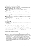
5 alignment guide 7 cable guides (4) 6 release tab Installing the Processor Airflow Shroud NOTICE: Ensure that all SATA/SAS cables are folded out of the way and that all power cables are properly routed before installing the processor airflow shroud. 1 Align the tabs on the processor airflow shroud with the tab slots on the chassis, then carefully lower the shroud into the chassis until the release tabs lock into place. Ensure that the alignment guide is seated in the corresponding hole in the chassis and that no cables are pinned under the bottom edges of the shroud (see Figure 3-8). 2 Route SATA cable(s) under and through the cable guides on the shroud. 3 Route the SAS cable, if applicable, under and through the cable guides on the shroud. 4 Reinstall the expansion card cover, if removed, and pivot the expansion card cover down until the cover snaps into place (see Figure 3-7). 5 Replace the system cover (see "Installing the System Cover" on page 67). Redundant and Non-Redundant Power Supplies Depending on your configuration, your system supports up to two hotpluggable redundant 528-W power supplies or a single non-redundant 490-W power supply. In redundant mode, the system distributes the power load across both power supplies to maximize efficiency. The second power supply provides power redundancy; thus, when a power supply is removed with the system powered on, the full power load is carried by the remaining power supply. For information on removing and installing redundant power supplies, see "Removing a Redundant Power Supply" on page 73 or "Installing a Redundant Power Supply" on page 75. For information on removing and installing a nonredundant power supply, see "Removing a Non-redundant Power Supply" on page 75 or "Installing a Non-Redundant Power Supply" on page 77. 72 Installing System Components
-
 1
1 -
2
-
3
-
4
-
5
-
6
-
7
-
8
-
9
-
10
-
11
-
12
-
13
-
14
-
15
-
16
-
17
-
18
-
19
-
20
-
21
-
22
-
23
-
24
-
25
-
26
-
27
-
28
-
29
-
30
-
31
-
32
-
33
-
34
-
35
-
36
-
37
-
38
-
39
-
40
-
41
-
42
-
43
-
44
-
45
-
46
-
47
-
48
-
49
-
50
-
51
-
52
-
53
-
54
-
55
-
56
-
57
-
58
-
59
-
60
-
61
-
62
-
63
-
64
-
65
-
66
-
 67
67 -
 68
68 -
 69
69 -
 70
70 -
 71
71 -
 72
72 -
 73
73 -
 74
74 -
 75
75 -
 76
76 -
 77
77 -
78
-
79
-
80
-
81
-
82
-
83
-
84
-
85
-
86
-
87
-
88
-
89
-
90
-
91
-
92
-
93
-
94
-
95
-
96
-
97
-
98
-
99
-
100
-
101
-
102
-
103
-
104
-
105
-
106
-
107
-
108
-
109
-
110
-
111
-
112
-
113
-
114
-
115
-
116
-
117
-
118
-
119
-
120
-
121
-
122
-
123
-
124
-
125
-
126
-
127
-
128
-
129
-
130
-
131
-
132
-
133
-
134
-
135
-
136
-
137
-
138
-
139
-
140
-
141
-
142
-
143
-
144
-
145
-
146
-
147
-
148
-
149
-
150
-
151
-
152
-
153
-
154
-
155
-
156
-
157
-
158
-
159
-
160
-
161
-
162
-
163
-
164
-
165
-
166
-
167
-
168
-
169
-
170
-
171
-
172
-
173
-
174
-
175
-
176
-
177
-
178
-
179
-
180
-
181
-
182
-
183
-
184
-
185
-
186
-
187
-
188
-
189
-
190
-
191
-
192
-
193
-
194
 |
 |
