Dell PowerEdge T300 Hardware Owner's Manual (PDF) - Page 98
Ensure that the card is fully seated in the guide slot.
 |
View all Dell PowerEdge T300 manuals
Add to My Manuals
Save this manual to your list of manuals |
Page 98 highlights
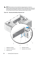
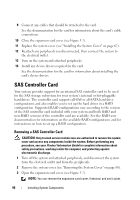
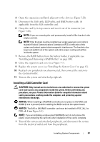
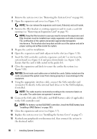
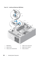
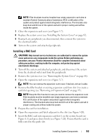
2 Remove the system cover (see "Removing the System Cover" on page 66). 3 Open the expansion card cover (see Figure 3-7). NOTE: You can remove the expansion card cover, if desired, and set it aside. 4 Remove the filler bracket or existing expansion card to create a card-slot opening (see "Removing an Expansion Card" on page 93). NOTE: Keep the filler bracket in case you need to remove the expansion card. Filler brackets must be installed over empty expansion card slots to maintain FCC certification of the system and protect against electromagnetic interference. The brackets also keep dust and dirt out of the system and aid in proper cooling and airflow inside the system. 5 Prepare the card for installation. 6 Open the expansion card latch adjacent to the slot (see Figure 3-20). 7 Insert the SAS controller card into expansion card slot 3 or slot 4 on the system board (see Figure 6-1) and press down firmly (see Figure 3-20). Ensure that the card is fully seated in the guide slot. 8 Close the expansion card latch to secure the card in the system (see Figure 3-20). NOTICE: Do not route card cables over or behind the cards. Cables routed over the cards can prevent the system cover from closing properly or cause damage to the equipment. 9 Using the appropriate interface cable, connect the SAS controller card (connector 0) directly to the internal hard drives or to the SAS backplane, if installed. NOTE: The cable must be connected according to the connector labels on the cable. The cable does not operate if reversed. 10 Connect the SAS cable, LED cable, and RAID battery cable (if applicable) to the SAS controller card. NOTE: For battery-cached SAS/RAID controllers, install the RAID battery (see "Installing a RAID Battery" on page 101). 11 Close the expansion card cover (see Figure 3-7). 12 Replace the system cover (see "Installing the System Cover" on page 67). 13 Reattach any peripherals you disconnected, then connect the system to the electrical outlet. 98 Installing System Components
-
 1
1 -
2
-
3
-
4
-
5
-
6
-
7
-
8
-
9
-
10
-
11
-
12
-
13
-
14
-
15
-
16
-
17
-
18
-
19
-
20
-
21
-
22
-
23
-
24
-
25
-
26
-
27
-
28
-
29
-
30
-
31
-
32
-
33
-
34
-
35
-
36
-
37
-
38
-
39
-
40
-
41
-
42
-
43
-
44
-
45
-
46
-
47
-
48
-
49
-
50
-
51
-
52
-
53
-
54
-
55
-
56
-
57
-
58
-
59
-
60
-
61
-
62
-
63
-
64
-
65
-
66
-
67
-
68
-
69
-
70
-
71
-
72
-
73
-
74
-
75
-
76
-
77
-
78
-
79
-
80
-
81
-
82
-
83
-
84
-
85
-
86
-
87
-
88
-
89
-
90
-
91
-
92
-
 93
93 -
 94
94 -
 95
95 -
 96
96 -
 97
97 -
 98
98 -
 99
99 -
 100
100 -
 101
101 -
 102
102 -
 103
103 -
104
-
105
-
106
-
107
-
108
-
109
-
110
-
111
-
112
-
113
-
114
-
115
-
116
-
117
-
118
-
119
-
120
-
121
-
122
-
123
-
124
-
125
-
126
-
127
-
128
-
129
-
130
-
131
-
132
-
133
-
134
-
135
-
136
-
137
-
138
-
139
-
140
-
141
-
142
-
143
-
144
-
145
-
146
-
147
-
148
-
149
-
150
-
151
-
152
-
153
-
154
-
155
-
156
-
157
-
158
-
159
-
160
-
161
-
162
-
163
-
164
-
165
-
166
-
167
-
168
-
169
-
170
-
171
-
172
-
173
-
174
-
175
-
176
-
177
-
178
-
179
-
180
-
181
-
182
-
183
-
184
-
185
-
186
-
187
-
188
-
189
-
190
-
191
-
192
-
193
-
194
 |
 |
