Dell PowerEdge T300 Hardware Owner's Manual (PDF) - Page 169
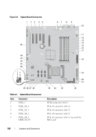
USB connectors USB1, USB2, and, NIC connectors LOM1_UP and LOM2
 |
View all Dell PowerEdge T300 manuals
Add to My Manuals
Save this manual to your list of manuals |
Page 169 highlights
Table 6-1. System Board Connectors (continued) Item Connector 6 J3 7 J4 8 VGA 9 COM 10 RAC_CONN 11 FAN2 12 DIMM1_A 13 DIMM1_B 14 DIMM2_A 15 DIMM2_B 16 DIMM3_A 17 DIMM3_B 18 FLOPPY 19 PWR_CONN 20 12V 21 PSU_12C 22 CTRL_PNL 23 CPU 24 BP_12C 25 USB_CONN 26 SATA_B 27 SATA_D 28 SATA_F 29 FAN1 30 INTRUSION Description USB connectors (USB1, USB2, USB3, and USB4) NIC connectors (LOM1_UP and LOM2_ DOWN) Video connector Serial connector Remote Access Controller (RAC) Rear system fan connector Memory module connector (slot 1) Memory module connector (slot 2) Memory module connector (slot 3) Memory module connector (slot 4) Memory module connector (slot 5) Memory module connector (slot 6) Diskette drive connector Main power connector Power connector Power distribution board connector Control panel connector Microprocessor connector Backplane connector Internal USB connector SATA drive connector SATA drive connector SATA drive connector Front system fan connector Chassis intrusion switch connector Jumpers and Connectors 169
-
 1
1 -
2
-
3
-
4
-
5
-
6
-
7
-
8
-
9
-
10
-
11
-
12
-
13
-
14
-
15
-
16
-
17
-
18
-
19
-
20
-
21
-
22
-
23
-
24
-
25
-
26
-
27
-
28
-
29
-
30
-
31
-
32
-
33
-
34
-
35
-
36
-
37
-
38
-
39
-
40
-
41
-
42
-
43
-
44
-
45
-
46
-
47
-
48
-
49
-
50
-
51
-
52
-
53
-
54
-
55
-
56
-
57
-
58
-
59
-
60
-
61
-
62
-
63
-
64
-
65
-
66
-
67
-
68
-
69
-
70
-
71
-
72
-
73
-
74
-
75
-
76
-
77
-
78
-
79
-
80
-
81
-
82
-
83
-
84
-
85
-
86
-
87
-
88
-
89
-
90
-
91
-
92
-
93
-
94
-
95
-
96
-
97
-
98
-
99
-
100
-
101
-
102
-
103
-
104
-
105
-
106
-
107
-
108
-
109
-
110
-
111
-
112
-
113
-
114
-
115
-
116
-
117
-
118
-
119
-
120
-
121
-
122
-
123
-
124
-
125
-
126
-
127
-
128
-
129
-
130
-
131
-
132
-
133
-
134
-
135
-
136
-
137
-
138
-
139
-
140
-
141
-
142
-
143
-
144
-
145
-
146
-
147
-
148
-
149
-
150
-
151
-
152
-
153
-
154
-
155
-
156
-
157
-
158
-
159
-
160
-
161
-
162
-
163
-
 164
164 -
 165
165 -
 166
166 -
 167
167 -
 168
168 -
 169
169 -
 170
170 -
 171
171 -
 172
172 -
 173
173 -
 174
174 -
175
-
176
-
177
-
178
-
179
-
180
-
181
-
182
-
183
-
184
-
185
-
186
-
187
-
188
-
189
-
190
-
191
-
192
-
193
-
194
 |
 |
