Dell PowerEdge T300 Hardware Owner's Manual (PDF) - Page 88
Optical and Tape Drives, Removing an Optical or Tape Drive
 |
View all Dell PowerEdge T300 manuals
Add to My Manuals
Save this manual to your list of manuals |
Page 88 highlights
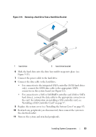
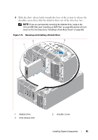
Optical and Tape Drives The 5.25-inch drive bays in the front of your system provide support for an optical drive and either an optional tape drive or second optical drive. Removing an Optical or Tape Drive CAUTION: Only trained service technicians are authorized to remove the system cover and access any components inside the system. Before performing any procedure, see your Product Information Guide for complete information about safety precautions, working inside the computer, and protecting against electrostatic discharge. 1 Turn off the system and attached peripherals, and disconnect the system from the electrical outlet and from the peripherals. 2 Remove the front bezel (see "Removing the Front Bezel" on page 63). 3 Remove the system cover (see "Removing the System Cover" on page 66). 4 Remove the processor airflow shroud (see "Removing the Processor Airflow Shroud" on page 70). 5 Disconnect the power and data cables from the back of the drive. See Figure 3-17 for disconnecting SCSI connections and Figure 3-18 for disconnecting SATA connections. 6 Slide the drive release latch towards the base of the system to release the shoulder screw, then slide the drive out of the drive bay. NOTE: If you are permanently removing the drive, replace the 5.25-inch EMI filler (see "Installing an EMI Filler" on page 69) and the 5.25-inch insert on the front bezel (see "Installing a Front Bezel Insert" on page 66). 88 Installing System Components
-
 1
1 -
2
-
3
-
4
-
5
-
6
-
7
-
8
-
9
-
10
-
11
-
12
-
13
-
14
-
15
-
16
-
17
-
18
-
19
-
20
-
21
-
22
-
23
-
24
-
25
-
26
-
27
-
28
-
29
-
30
-
31
-
32
-
33
-
34
-
35
-
36
-
37
-
38
-
39
-
40
-
41
-
42
-
43
-
44
-
45
-
46
-
47
-
48
-
49
-
50
-
51
-
52
-
53
-
54
-
55
-
56
-
57
-
58
-
59
-
60
-
61
-
62
-
63
-
64
-
65
-
66
-
67
-
68
-
69
-
70
-
71
-
72
-
73
-
74
-
75
-
76
-
77
-
78
-
79
-
80
-
81
-
82
-
 83
83 -
 84
84 -
 85
85 -
 86
86 -
 87
87 -
 88
88 -
 89
89 -
 90
90 -
 91
91 -
 92
92 -
 93
93 -
94
-
95
-
96
-
97
-
98
-
99
-
100
-
101
-
102
-
103
-
104
-
105
-
106
-
107
-
108
-
109
-
110
-
111
-
112
-
113
-
114
-
115
-
116
-
117
-
118
-
119
-
120
-
121
-
122
-
123
-
124
-
125
-
126
-
127
-
128
-
129
-
130
-
131
-
132
-
133
-
134
-
135
-
136
-
137
-
138
-
139
-
140
-
141
-
142
-
143
-
144
-
145
-
146
-
147
-
148
-
149
-
150
-
151
-
152
-
153
-
154
-
155
-
156
-
157
-
158
-
159
-
160
-
161
-
162
-
163
-
164
-
165
-
166
-
167
-
168
-
169
-
170
-
171
-
172
-
173
-
174
-
175
-
176
-
177
-
178
-
179
-
180
-
181
-
182
-
183
-
184
-
185
-
186
-
187
-
188
-
189
-
190
-
191
-
192
-
193
-
194
 |
 |
