Dell PowerEdge T300 Hardware Owner's Manual (PDF) - Page 93
Expansion Cards, Removing an Expansion Card
 |
View all Dell PowerEdge T300 manuals
Add to My Manuals
Save this manual to your list of manuals |
Page 93 highlights
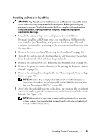
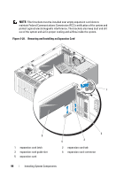
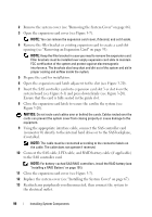
12 Replace the system cover (see "Installing the System Cover" on page 67). 13 Replace the front bezel (see "Installing the Front Bezel" on page 64). 14 Enter the System Setup program and ensure that the drive's controller is enabled (see "Entering the System Setup Program" on page 41). Expansion Cards The system board can accommodate up to five expansion cards (see Figure 6-1): • One 3.3-V, full-length PCI-X (slot 5) • One 3.3-V, full-length PCIe x4 (slot 2) • One 3.3-V, full-length PCIe x4 with x8 connector (slot 1) • Two 3.3-V, full-length PCIe x8 (slots 3 and 4) NOTE: Slot 1 is reserved for an optional RAC card. NOTE: A SAS controller card may be installed in slot 3 or 4; however, a PERC 6/iR card, if used, must be installed in slot 3. Removing an Expansion Card CAUTION: Only trained service technicians are authorized to remove the system cover and access any components inside the system. Before performing any procedure, see your Product Information Guide for complete information about safety precautions, working inside the computer, and protecting against electrostatic discharge. 1 Turn off the system and attached peripherals, and disconnect the system from the electrical outlet and from the peripherals. 2 Remove the system cover (see "Removing the System Cover" on page 66). 3 Open the expansion card cover (see Figure 3-7). NOTE: You can remove the expansion card cover, if desired, and set it aside. 4 Open the expansion card latch adjacent to the slot (see Figure 3-20). 5 Disconnect any cables connected to the card. 6 Grasp the card by its top corners and ease it out of its connector. NOTE: If you are removing the card permanently, install a filler bracket in the empty card slot. Installing System Components 93
-
 1
1 -
2
-
3
-
4
-
5
-
6
-
7
-
8
-
9
-
10
-
11
-
12
-
13
-
14
-
15
-
16
-
17
-
18
-
19
-
20
-
21
-
22
-
23
-
24
-
25
-
26
-
27
-
28
-
29
-
30
-
31
-
32
-
33
-
34
-
35
-
36
-
37
-
38
-
39
-
40
-
41
-
42
-
43
-
44
-
45
-
46
-
47
-
48
-
49
-
50
-
51
-
52
-
53
-
54
-
55
-
56
-
57
-
58
-
59
-
60
-
61
-
62
-
63
-
64
-
65
-
66
-
67
-
68
-
69
-
70
-
71
-
72
-
73
-
74
-
75
-
76
-
77
-
78
-
79
-
80
-
81
-
82
-
83
-
84
-
85
-
86
-
87
-
 88
88 -
 89
89 -
 90
90 -
 91
91 -
 92
92 -
 93
93 -
 94
94 -
 95
95 -
 96
96 -
 97
97 -
 98
98 -
99
-
100
-
101
-
102
-
103
-
104
-
105
-
106
-
107
-
108
-
109
-
110
-
111
-
112
-
113
-
114
-
115
-
116
-
117
-
118
-
119
-
120
-
121
-
122
-
123
-
124
-
125
-
126
-
127
-
128
-
129
-
130
-
131
-
132
-
133
-
134
-
135
-
136
-
137
-
138
-
139
-
140
-
141
-
142
-
143
-
144
-
145
-
146
-
147
-
148
-
149
-
150
-
151
-
152
-
153
-
154
-
155
-
156
-
157
-
158
-
159
-
160
-
161
-
162
-
163
-
164
-
165
-
166
-
167
-
168
-
169
-
170
-
171
-
172
-
173
-
174
-
175
-
176
-
177
-
178
-
179
-
180
-
181
-
182
-
183
-
184
-
185
-
186
-
187
-
188
-
189
-
190
-
191
-
192
-
193
-
194
 |
 |
