Dell PowerEdge T300 Hardware Owner's Manual (PDF) - Page 130
Installing the System Board, release pin locks into place see
 |
View all Dell PowerEdge T300 manuals
Add to My Manuals
Save this manual to your list of manuals |
Page 130 highlights
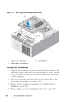
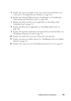
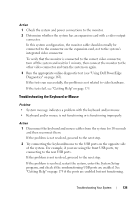
Figure 3-34. Removing and Installing the System Board 2 1 3 1 system board release pin 3 system board securing slots 2 system board Installing the System Board 1 Align the back connectors on the system board with the cutouts in the back of the chassis, and ensure the system board tray is square with the chassis so that the securing tabs on the chassis fully insert into system board securing slots. 2 Slide the system board towards the back of the system until the blue release pin locks into place (see Figure 3-34). 3 Replace the SAS backplane, if applicable (see "Installing the SAS Backplane" on page 126). 4 Replace the processor (see "Installing the Processor" on page 117). 130 Installing System Components
-
 1
1 -
2
-
3
-
4
-
5
-
6
-
7
-
8
-
9
-
10
-
11
-
12
-
13
-
14
-
15
-
16
-
17
-
18
-
19
-
20
-
21
-
22
-
23
-
24
-
25
-
26
-
27
-
28
-
29
-
30
-
31
-
32
-
33
-
34
-
35
-
36
-
37
-
38
-
39
-
40
-
41
-
42
-
43
-
44
-
45
-
46
-
47
-
48
-
49
-
50
-
51
-
52
-
53
-
54
-
55
-
56
-
57
-
58
-
59
-
60
-
61
-
62
-
63
-
64
-
65
-
66
-
67
-
68
-
69
-
70
-
71
-
72
-
73
-
74
-
75
-
76
-
77
-
78
-
79
-
80
-
81
-
82
-
83
-
84
-
85
-
86
-
87
-
88
-
89
-
90
-
91
-
92
-
93
-
94
-
95
-
96
-
97
-
98
-
99
-
100
-
101
-
102
-
103
-
104
-
105
-
106
-
107
-
108
-
109
-
110
-
111
-
112
-
113
-
114
-
115
-
116
-
117
-
118
-
119
-
120
-
121
-
122
-
123
-
124
-
 125
125 -
 126
126 -
 127
127 -
 128
128 -
 129
129 -
 130
130 -
 131
131 -
 132
132 -
 133
133 -
 134
134 -
 135
135 -
136
-
137
-
138
-
139
-
140
-
141
-
142
-
143
-
144
-
145
-
146
-
147
-
148
-
149
-
150
-
151
-
152
-
153
-
154
-
155
-
156
-
157
-
158
-
159
-
160
-
161
-
162
-
163
-
164
-
165
-
166
-
167
-
168
-
169
-
170
-
171
-
172
-
173
-
174
-
175
-
176
-
177
-
178
-
179
-
180
-
181
-
182
-
183
-
184
-
185
-
186
-
187
-
188
-
189
-
190
-
191
-
192
-
193
-
194
 |
 |

130
Installing System Components
Figure 3-34.
Removing and Installing the System Board
Installing the System Board
1
Align the back connectors on the system board with the cutouts in the
back of the chassis, and ensure the system board tray is square with the
chassis so that the securing tabs on the chassis fully insert into system
board securing slots.
2
Slide the system board towards the back of the system until the blue
release pin locks into place (see Figure 3-34).
3
Replace the SAS backplane, if applicable (see "Installing the SAS
Backplane" on page 126).
4
Replace the processor (see "Installing the Processor" on page 117).
1
system board release pin
2
system board
3
system board securing slots
1
2
3