Dell PowerEdge T300 Hardware Owner's Manual (PDF) - Page 120
Installing the System Battery, Chassis Intrusion Switch, Removing the Chassis Intrusion Switch
 |
View all Dell PowerEdge T300 manuals
Add to My Manuals
Save this manual to your list of manuals |
Page 120 highlights
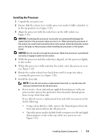
Installing the System Battery NOTICE: To avoid damage to the battery connector, you must firmly support the connector while installing or removing a battery. 1 Support the battery connector by pressing down firmly on the positive side of the connector. 2 Hold the battery with the "+" facing up, and slide it under the securing tabs at the positive side of the connector. 3 Press the battery straight down into the connector until it snaps into place (see Figure 3-29). 4 Close the expansion card cover (see Figure 3-7). 5 Replace the system cover (see "Installing the System Cover" on page 67). 6 Place the system upright on a flat, stable surface. 7 Rotate the system feet outward into the open position (see Figure 3-5). 8 Reattach any peripherals you disconnected, then connect the system to the electrical outlet. 9 Turn on the system and attached peripherals. 10 Enter the System Setup program to confirm that the battery is operating properly (see "Entering the System Setup Program" on page 41). 11 Enter the correct time and date in the System Setup program's Time and Date fields. 12 Exit the System Setup program. NOTE: To test the newly installed battery, turn off the system and disconnect it from the electrical outlet for at least an hour, then reconnect the system to its electrical outlet and turn it on. Chassis Intrusion Switch Removing the Chassis Intrusion Switch CAUTION: Only trained service technicians are authorized to remove the system cover and access any components inside the system. Before performing any procedure, see your Product Information Guide for complete information about safety precautions, working inside the computer, and protecting against electrostatic discharge. 120 Installing System Components
-
 1
1 -
2
-
3
-
4
-
5
-
6
-
7
-
8
-
9
-
10
-
11
-
12
-
13
-
14
-
15
-
16
-
17
-
18
-
19
-
20
-
21
-
22
-
23
-
24
-
25
-
26
-
27
-
28
-
29
-
30
-
31
-
32
-
33
-
34
-
35
-
36
-
37
-
38
-
39
-
40
-
41
-
42
-
43
-
44
-
45
-
46
-
47
-
48
-
49
-
50
-
51
-
52
-
53
-
54
-
55
-
56
-
57
-
58
-
59
-
60
-
61
-
62
-
63
-
64
-
65
-
66
-
67
-
68
-
69
-
70
-
71
-
72
-
73
-
74
-
75
-
76
-
77
-
78
-
79
-
80
-
81
-
82
-
83
-
84
-
85
-
86
-
87
-
88
-
89
-
90
-
91
-
92
-
93
-
94
-
95
-
96
-
97
-
98
-
99
-
100
-
101
-
102
-
103
-
104
-
105
-
106
-
107
-
108
-
109
-
110
-
111
-
112
-
113
-
114
-
 115
115 -
 116
116 -
 117
117 -
 118
118 -
 119
119 -
 120
120 -
 121
121 -
 122
122 -
 123
123 -
 124
124 -
 125
125 -
126
-
127
-
128
-
129
-
130
-
131
-
132
-
133
-
134
-
135
-
136
-
137
-
138
-
139
-
140
-
141
-
142
-
143
-
144
-
145
-
146
-
147
-
148
-
149
-
150
-
151
-
152
-
153
-
154
-
155
-
156
-
157
-
158
-
159
-
160
-
161
-
162
-
163
-
164
-
165
-
166
-
167
-
168
-
169
-
170
-
171
-
172
-
173
-
174
-
175
-
176
-
177
-
178
-
179
-
180
-
181
-
182
-
183
-
184
-
185
-
186
-
187
-
188
-
189
-
190
-
191
-
192
-
193
-
194
 |
 |
