Dell PowerEdge T300 Hardware Owner's Manual (PDF) - Page 110
System Memory, Memory Module Installation Guidelines - processor upgrade
 |
View all Dell PowerEdge T300 manuals
Add to My Manuals
Save this manual to your list of manuals |
Page 110 highlights
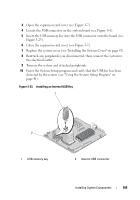
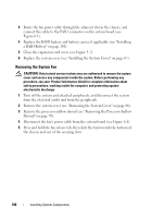
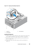
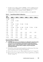
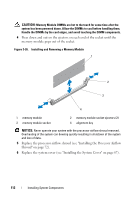
4 Replace the processor airflow shroud (see "Installing the Processor Airflow Shroud" on page 72). 5 Replace the system cover (see "Installing the System Cover" on page 67). System Memory The six memory module sockets are located on the system board adjacent to the power supply and can accommodate 512 MB to 24 GB of registered PC2-4200/5300, 533/667-MHz, DDR2 memory with ECC. See Figure 6-1 for the location of the memory module sockets. You can upgrade the system memory by installing combinations of 512-MB, 1-GB, 2-GB, and 4-GB memory modules. You can purchase memory upgrade kits from Dell. NOTE: Memory modules must be PC2-4200/5300 compliant for your system. Memory Module Installation Guidelines The memory module sockets are arranged in three banks (1, 2, and 3) on two channels (A and B). The memory module banks are identified as follows: Bank 1: DIMM1_A and DIMM1_B Bank 2: DIMM2_A and DIMM2_B Bank 3: DIMM3_A and DIMM3_B Memory modules must be installed in memory module banks in identical pairs for configurations with more than one memory module. For example, if socket DIMM1_A contains a 512-MB memory module, then the second memory module to be installed must be a 512-MB memory module in socket DIMM1_B. Table 3-1 shows examples of different memory configurations, based on the following guidelines: • The minimum memory configuration is 512 MB. • If only one memory module is installed, it must be installed in the DIMM1_A socket. • A memory module bank must contain identical memory modules. 110 Installing System Components
-
 1
1 -
2
-
3
-
4
-
5
-
6
-
7
-
8
-
9
-
10
-
11
-
12
-
13
-
14
-
15
-
16
-
17
-
18
-
19
-
20
-
21
-
22
-
23
-
24
-
25
-
26
-
27
-
28
-
29
-
30
-
31
-
32
-
33
-
34
-
35
-
36
-
37
-
38
-
39
-
40
-
41
-
42
-
43
-
44
-
45
-
46
-
47
-
48
-
49
-
50
-
51
-
52
-
53
-
54
-
55
-
56
-
57
-
58
-
59
-
60
-
61
-
62
-
63
-
64
-
65
-
66
-
67
-
68
-
69
-
70
-
71
-
72
-
73
-
74
-
75
-
76
-
77
-
78
-
79
-
80
-
81
-
82
-
83
-
84
-
85
-
86
-
87
-
88
-
89
-
90
-
91
-
92
-
93
-
94
-
95
-
96
-
97
-
98
-
99
-
100
-
101
-
102
-
103
-
104
-
 105
105 -
 106
106 -
 107
107 -
 108
108 -
 109
109 -
 110
110 -
 111
111 -
 112
112 -
 113
113 -
 114
114 -
 115
115 -
116
-
117
-
118
-
119
-
120
-
121
-
122
-
123
-
124
-
125
-
126
-
127
-
128
-
129
-
130
-
131
-
132
-
133
-
134
-
135
-
136
-
137
-
138
-
139
-
140
-
141
-
142
-
143
-
144
-
145
-
146
-
147
-
148
-
149
-
150
-
151
-
152
-
153
-
154
-
155
-
156
-
157
-
158
-
159
-
160
-
161
-
162
-
163
-
164
-
165
-
166
-
167
-
168
-
169
-
170
-
171
-
172
-
173
-
174
-
175
-
176
-
177
-
178
-
179
-
180
-
181
-
182
-
183
-
184
-
185
-
186
-
187
-
188
-
189
-
190
-
191
-
192
-
193
-
194
 |
 |
