Dell PowerEdge T300 Hardware Owner's Manual (PDF) - Page 112
Replace the processor airflow shroud see Installing the Processor Airflow
 |
View all Dell PowerEdge T300 manuals
Add to My Manuals
Save this manual to your list of manuals |
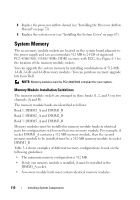
Page 112 highlights
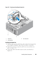
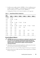
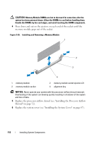
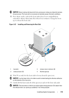
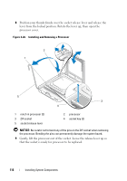
CAUTION: Memory Module DIMMs are hot to the touch for some time after the system has been powered down. Allow the DIMMs to cool before handling them. Handle the DIMMs by the card edges, and avoid touching the DIMM components. 4 Press down and out on the ejectors on each end of the socket until the memory module pops out of the socket. Figure 3-26. Installing and Removing a Memory Module 1 2 3 4 1 memory module 3 memory module socket 2 memory module socket ejectors (2) 4 alignment key NOTICE: Never operate your system with the processor airflow shroud removed. Overheating of the system can develop quickly resulting in shutdown of the system and loss of data. 5 Replace the processor airflow shroud (see "Installing the Processor Airflow Shroud" on page 72). 6 Replace the system cover (see "Installing the System Cover" on page 67). 112 Installing System Components
-
 1
1 -
2
-
3
-
4
-
5
-
6
-
7
-
8
-
9
-
10
-
11
-
12
-
13
-
14
-
15
-
16
-
17
-
18
-
19
-
20
-
21
-
22
-
23
-
24
-
25
-
26
-
27
-
28
-
29
-
30
-
31
-
32
-
33
-
34
-
35
-
36
-
37
-
38
-
39
-
40
-
41
-
42
-
43
-
44
-
45
-
46
-
47
-
48
-
49
-
50
-
51
-
52
-
53
-
54
-
55
-
56
-
57
-
58
-
59
-
60
-
61
-
62
-
63
-
64
-
65
-
66
-
67
-
68
-
69
-
70
-
71
-
72
-
73
-
74
-
75
-
76
-
77
-
78
-
79
-
80
-
81
-
82
-
83
-
84
-
85
-
86
-
87
-
88
-
89
-
90
-
91
-
92
-
93
-
94
-
95
-
96
-
97
-
98
-
99
-
100
-
101
-
102
-
103
-
104
-
105
-
106
-
 107
107 -
 108
108 -
 109
109 -
 110
110 -
 111
111 -
 112
112 -
 113
113 -
 114
114 -
 115
115 -
 116
116 -
 117
117 -
118
-
119
-
120
-
121
-
122
-
123
-
124
-
125
-
126
-
127
-
128
-
129
-
130
-
131
-
132
-
133
-
134
-
135
-
136
-
137
-
138
-
139
-
140
-
141
-
142
-
143
-
144
-
145
-
146
-
147
-
148
-
149
-
150
-
151
-
152
-
153
-
154
-
155
-
156
-
157
-
158
-
159
-
160
-
161
-
162
-
163
-
164
-
165
-
166
-
167
-
168
-
169
-
170
-
171
-
172
-
173
-
174
-
175
-
176
-
177
-
178
-
179
-
180
-
181
-
182
-
183
-
184
-
185
-
186
-
187
-
188
-
189
-
190
-
191
-
192
-
193
-
194
 |
 |
