Dell PowerEdge T300 Hardware Owner's Manual (PDF) - Page 80
Removing a Cabled Hard Drive, the handle up until it snaps into place see - hard drive carrier
 |
View all Dell PowerEdge T300 manuals
Add to My Manuals
Save this manual to your list of manuals |
Page 80 highlights
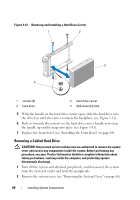
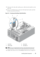
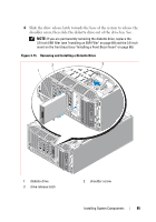
Figure 3-12. Removing and Installing a Hard Drive Carrier 1 2 3 4 1 screws (4) 3 hard drive 2 hard drive carrier 4 SAS mounting hole 5 With the handle on the hard drive carrier open, slide the hard drive into the drive bay until the carrier contacts the backplane (see Figure 3-11). 6 Push in (towards the system) on the hard drive carrier handle and rotate the handle up until it snaps into place (see Figure 3-11). 7 Replace the front bezel (see "Installing the Front Bezel" on page 64). Removing a Cabled Hard Drive CAUTION: Only trained service technicians are authorized to remove the system cover and access any components inside the system. Before performing any procedure, see your Product Information Guide for complete information about safety precautions, working inside the computer, and protecting against electrostatic discharge. 1 Turn off the system and attached peripherals, and disconnect the system from the electrical outlet and from the peripherals. 2 Remove the system cover (see "Removing the System Cover" on page 66). 80 Installing System Components
-
 1
1 -
2
-
3
-
4
-
5
-
6
-
7
-
8
-
9
-
10
-
11
-
12
-
13
-
14
-
15
-
16
-
17
-
18
-
19
-
20
-
21
-
22
-
23
-
24
-
25
-
26
-
27
-
28
-
29
-
30
-
31
-
32
-
33
-
34
-
35
-
36
-
37
-
38
-
39
-
40
-
41
-
42
-
43
-
44
-
45
-
46
-
47
-
48
-
49
-
50
-
51
-
52
-
53
-
54
-
55
-
56
-
57
-
58
-
59
-
60
-
61
-
62
-
63
-
64
-
65
-
66
-
67
-
68
-
69
-
70
-
71
-
72
-
73
-
74
-
 75
75 -
 76
76 -
 77
77 -
 78
78 -
 79
79 -
 80
80 -
 81
81 -
 82
82 -
 83
83 -
 84
84 -
 85
85 -
86
-
87
-
88
-
89
-
90
-
91
-
92
-
93
-
94
-
95
-
96
-
97
-
98
-
99
-
100
-
101
-
102
-
103
-
104
-
105
-
106
-
107
-
108
-
109
-
110
-
111
-
112
-
113
-
114
-
115
-
116
-
117
-
118
-
119
-
120
-
121
-
122
-
123
-
124
-
125
-
126
-
127
-
128
-
129
-
130
-
131
-
132
-
133
-
134
-
135
-
136
-
137
-
138
-
139
-
140
-
141
-
142
-
143
-
144
-
145
-
146
-
147
-
148
-
149
-
150
-
151
-
152
-
153
-
154
-
155
-
156
-
157
-
158
-
159
-
160
-
161
-
162
-
163
-
164
-
165
-
166
-
167
-
168
-
169
-
170
-
171
-
172
-
173
-
174
-
175
-
176
-
177
-
178
-
179
-
180
-
181
-
182
-
183
-
184
-
185
-
186
-
187
-
188
-
189
-
190
-
191
-
192
-
193
-
194
 |
 |
