Dell PowerEdge T300 Hardware Owner's Manual (PDF) - Page 75
Installing a Redundant Power Supply - manual
 |
View all Dell PowerEdge T300 manuals
Add to My Manuals
Save this manual to your list of manuals |
Page 75 highlights
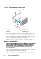
Installing a Redundant Power Supply NOTE: When installing a redundant power supply, allow several seconds for the system to recognize the power supply and determine if it is functioning properly. 1 With the power supply handle in the extended position, slide the power supply into the chassis (see Figure 3-9). 2 Press down on the power supply handle until the the locking tab snaps into place (see Figure 3-9). NOTE: You may have to manually press the locking tab into place in order to secure the power supply. 3 Connect the power cable to the power supply. 4 Route the power cable through the cable retention bracket (see Figure 3-9). 5 Connect the power cable to the electrical outlet. The power supply status indicator turns green if the power supply is functioning properly (see Figure 1-3). Removing a Non-redundant Power Supply CAUTION: Only trained service technicians are authorized to remove the system cover and access any components inside the system. Before performing any procedure, see your Product Information Guide for complete information about safety precautions, working inside the computer, and protecting against electrostatic discharge. 1 Turn off the system and attached peripherals, and disconnect the system from the electrical outlet and from the peripherals. 2 Remove the system cover (see "Removing the System Cover" on page 66). 3 Remove the processor airflow shroud (see "Removing the Processor Airflow Shroud" on page 70). 4 Disconnect all power cables from the system board, drives, and SAS backplane (if installed). Note the routing of the power cables as you disconnect the cables from the system board and drives. You must route these cables properly when you replace them to prevent them from being pinched or crimped. Installing System Components 75
-
 1
1 -
2
-
3
-
4
-
5
-
6
-
7
-
8
-
9
-
10
-
11
-
12
-
13
-
14
-
15
-
16
-
17
-
18
-
19
-
20
-
21
-
22
-
23
-
24
-
25
-
26
-
27
-
28
-
29
-
30
-
31
-
32
-
33
-
34
-
35
-
36
-
37
-
38
-
39
-
40
-
41
-
42
-
43
-
44
-
45
-
46
-
47
-
48
-
49
-
50
-
51
-
52
-
53
-
54
-
55
-
56
-
57
-
58
-
59
-
60
-
61
-
62
-
63
-
64
-
65
-
66
-
67
-
68
-
69
-
 70
70 -
 71
71 -
 72
72 -
 73
73 -
 74
74 -
 75
75 -
 76
76 -
 77
77 -
 78
78 -
 79
79 -
 80
80 -
81
-
82
-
83
-
84
-
85
-
86
-
87
-
88
-
89
-
90
-
91
-
92
-
93
-
94
-
95
-
96
-
97
-
98
-
99
-
100
-
101
-
102
-
103
-
104
-
105
-
106
-
107
-
108
-
109
-
110
-
111
-
112
-
113
-
114
-
115
-
116
-
117
-
118
-
119
-
120
-
121
-
122
-
123
-
124
-
125
-
126
-
127
-
128
-
129
-
130
-
131
-
132
-
133
-
134
-
135
-
136
-
137
-
138
-
139
-
140
-
141
-
142
-
143
-
144
-
145
-
146
-
147
-
148
-
149
-
150
-
151
-
152
-
153
-
154
-
155
-
156
-
157
-
158
-
159
-
160
-
161
-
162
-
163
-
164
-
165
-
166
-
167
-
168
-
169
-
170
-
171
-
172
-
173
-
174
-
175
-
176
-
177
-
178
-
179
-
180
-
181
-
182
-
183
-
184
-
185
-
186
-
187
-
188
-
189
-
190
-
191
-
192
-
193
-
194
 |
 |
