Dell PowerEdge T300 Hardware Owner's Manual (PDF) - Page 129
Backplane on Remove the SAS backplane, if applicable see Removing the SAS
 |
View all Dell PowerEdge T300 manuals
Add to My Manuals
Save this manual to your list of manuals |
Page 129 highlights
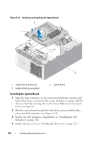
7 Remove the SAS controller card, if applicable (see "RAID Battery" on page 99). 8 Remove the internal USB memory key, if applicable (see Figure 6-1). 9 Remove all memory modules (see "Removing Memory Modules" on page 111). NOTE: Record the memory module socket locations to ensure proper reinstallation of the memory modules. CAUTION: The processor and heat sink can become extremely hot. Allow sufficient time for the processor and heat sink to cool before handling. NOTICE: To prevent damaging the processor, do not pry the heat sink off of the processor. 10 Remove the processor (see "Removing the Processor" on page 114). 11 Remove the SAS backplane, if applicable (see "Removing the SAS Backplane" on page 124). 12 Carefully route any loose cables away from the edges of the system board. 13 Pull up on the system board release pin, then slide the system board assembly toward the front of the system. 14 Lift the system board out of the system. Installing System Components 129
-
 1
1 -
2
-
3
-
4
-
5
-
6
-
7
-
8
-
9
-
10
-
11
-
12
-
13
-
14
-
15
-
16
-
17
-
18
-
19
-
20
-
21
-
22
-
23
-
24
-
25
-
26
-
27
-
28
-
29
-
30
-
31
-
32
-
33
-
34
-
35
-
36
-
37
-
38
-
39
-
40
-
41
-
42
-
43
-
44
-
45
-
46
-
47
-
48
-
49
-
50
-
51
-
52
-
53
-
54
-
55
-
56
-
57
-
58
-
59
-
60
-
61
-
62
-
63
-
64
-
65
-
66
-
67
-
68
-
69
-
70
-
71
-
72
-
73
-
74
-
75
-
76
-
77
-
78
-
79
-
80
-
81
-
82
-
83
-
84
-
85
-
86
-
87
-
88
-
89
-
90
-
91
-
92
-
93
-
94
-
95
-
96
-
97
-
98
-
99
-
100
-
101
-
102
-
103
-
104
-
105
-
106
-
107
-
108
-
109
-
110
-
111
-
112
-
113
-
114
-
115
-
116
-
117
-
118
-
119
-
120
-
121
-
122
-
123
-
 124
124 -
 125
125 -
 126
126 -
 127
127 -
 128
128 -
 129
129 -
 130
130 -
 131
131 -
 132
132 -
 133
133 -
 134
134 -
135
-
136
-
137
-
138
-
139
-
140
-
141
-
142
-
143
-
144
-
145
-
146
-
147
-
148
-
149
-
150
-
151
-
152
-
153
-
154
-
155
-
156
-
157
-
158
-
159
-
160
-
161
-
162
-
163
-
164
-
165
-
166
-
167
-
168
-
169
-
170
-
171
-
172
-
173
-
174
-
175
-
176
-
177
-
178
-
179
-
180
-
181
-
182
-
183
-
184
-
185
-
186
-
187
-
188
-
189
-
190
-
191
-
192
-
193
-
194
 |
 |
